
Tuner4TRONIC Production 4 (T4T-P4) - User Manual
Set up T4T-P4, program drivers from Production Files, read and clone drivers, inspect monitoring data, and configure label printing.
Updated · by Administrator
On this page
- Please note
- 1 About Tuner4TRONIC
- 1.1 Purpose and application
- 1.2 File types
- 1.3 Workflow between T4T tools
- 1.4 System requirements
- 1.5 Programming interfaces
- 1.6 Prepare a driver with a DALI interface
- 1.7 Prepare a driver with an NFC interface
- 1.8 Prepare a driver with a Prog+/Prog- interface
- 1.9 Prepare a driver with a DA+(P+)/DA-(P-) interface
- 1.10 Software installation
- 2 Using T4T Production
- Appendix - Monitoring Data v2
- Service contact
Tuner4TRONIC Production 4 (T4T-P4) - User Manual

This manual is based on the July 2024 Tuner4TRONIC Production 4 user manual.
Please note
All information in this guide has been prepared with great care. Inventronics, however, does not accept liability for possible errors, changes and/or omissions. Please check www.inventronicsglobal.com or contact your sales partner for an updated copy of this guide.
This technical application guide is for information purposes only and aims to support you in tackling the challenges and taking full advantage of all opportunities the technology has to offer. It is based on Inventronics' own measurements, tests, specific parameters and assumptions. Individual applications may not be covered and may need different handling. Responsibility and testing obligations remain with the luminaire manufacturer/OEM/application planner.
1 About Tuner4TRONIC
1.1 Purpose and application
The Tuner4TRONIC (T4T) software suite allows luminaire manufacturers to program Inventronics drivers via DALI and/or NFC in a simple, fast, reliable and cost-effective way, speeding up production. Download the tools from the Inventronics Tuner4TRONIC page.
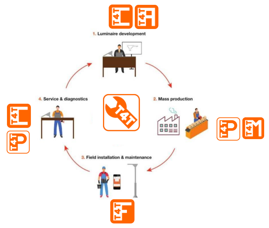
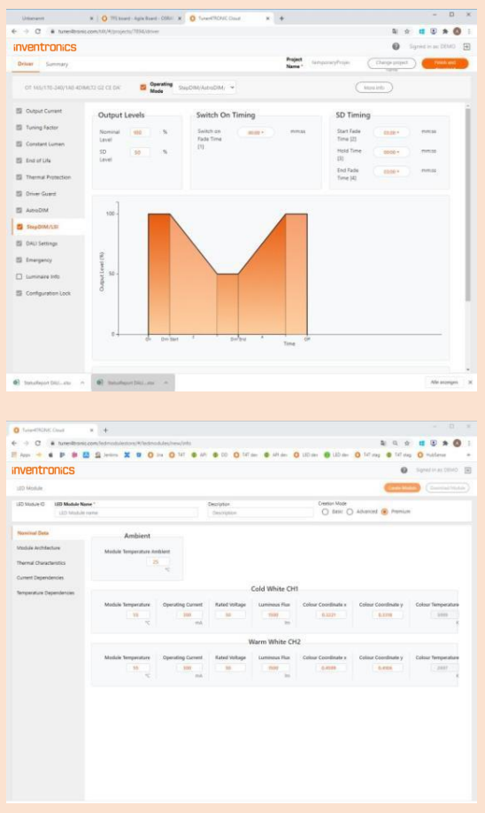
Tuner4TRONIC Configurator
This browser application lets luminaire designers configure LED driver output current, dimming levels, constant lumen output (CLO), operating modes and other parameters. Its multi-level password system, Configuration Lock, protects drivers against unauthorized changes while granting service technicians access to selected features.
Export the completed settings as an encrypted, read-only Production File and send it to the production line. The Tuner4TRONIC website also provides a TW LED Module Editor for customized tunable-white LED module settings.
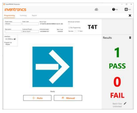
Tuner4TRONIC Production
Upload encrypted Production Files from T4T Configurator into LED drivers for fast mass production. T4T Production also reads driver data for display and editing in T4T Configurator.
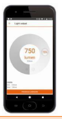
Tuner4TRONIC Field
This smartphone app programs indoor and outdoor Inventronics LED drivers via NFC, wirelessly and without mains voltage. It adjusts light output, CLO and dimming profiles, uploads Production Files created by T4T Configurator, and copies data between drivers for on-site replacement.
See the Field App user manual for details.
Tuner4TRONIC REST API
The REST API gives software developers functions and tools to create luminaire configurations automatically, for example when a new order becomes available in an ERP system. It comes with comprehensive documentation.
Tuner4TRONIC Machine
DLL and command line tools integrate LED driver programming into automatic programming stations in the production line.
See the T4T-CMD 4 user manual for command line operation.
1.2 File types
| File type | Extension |
|---|---|
| Tuner4TRONIC Production File | .osrtup |
| Driver description file | .osrtud |
| Driver readback data | .osrtur |
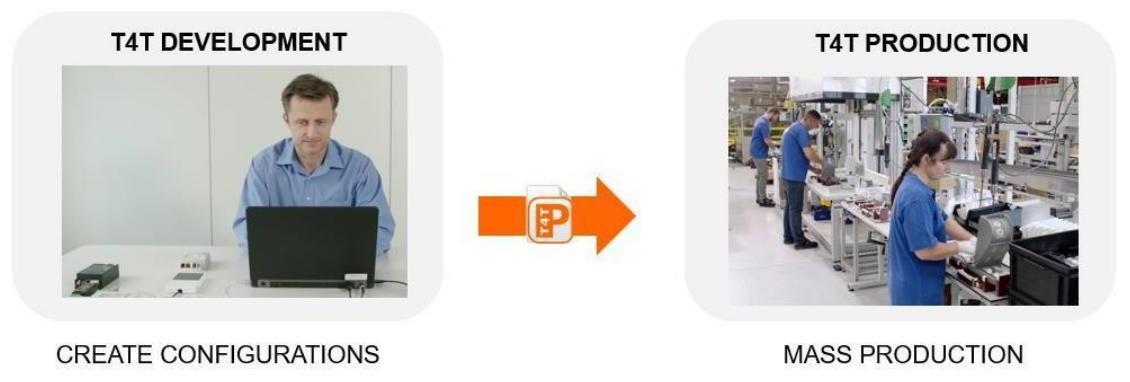
1.3 Workflow between T4T tools
- Create the desired configuration, such as operating current, CLO and dimming, in T4T Configurator.
- Create and download a read-only
.osrtupProduction File for T4T Production on the assembly line. - For testing and diagnostics, read data back from the driver in T4T Production and import the
.osrturfile into T4T Configurator for visualization.
The optional API creates luminaire and Production Files directly from an ERP system, removing the need to create them manually.
1.4 System requirements
Minimum requirements listed in the July 2024 manual:
- 1 GB main memory.
- Windows 8, Windows 8.1 or Windows 10, 32-bit or 64-bit, with the latest service pack installed.
- 200 MB hard disk space.
- Monitor resolution of 1024 × 768 pixels; recommended zoom factor: 100%.
- One free USB 2.0 port for the programming interface.
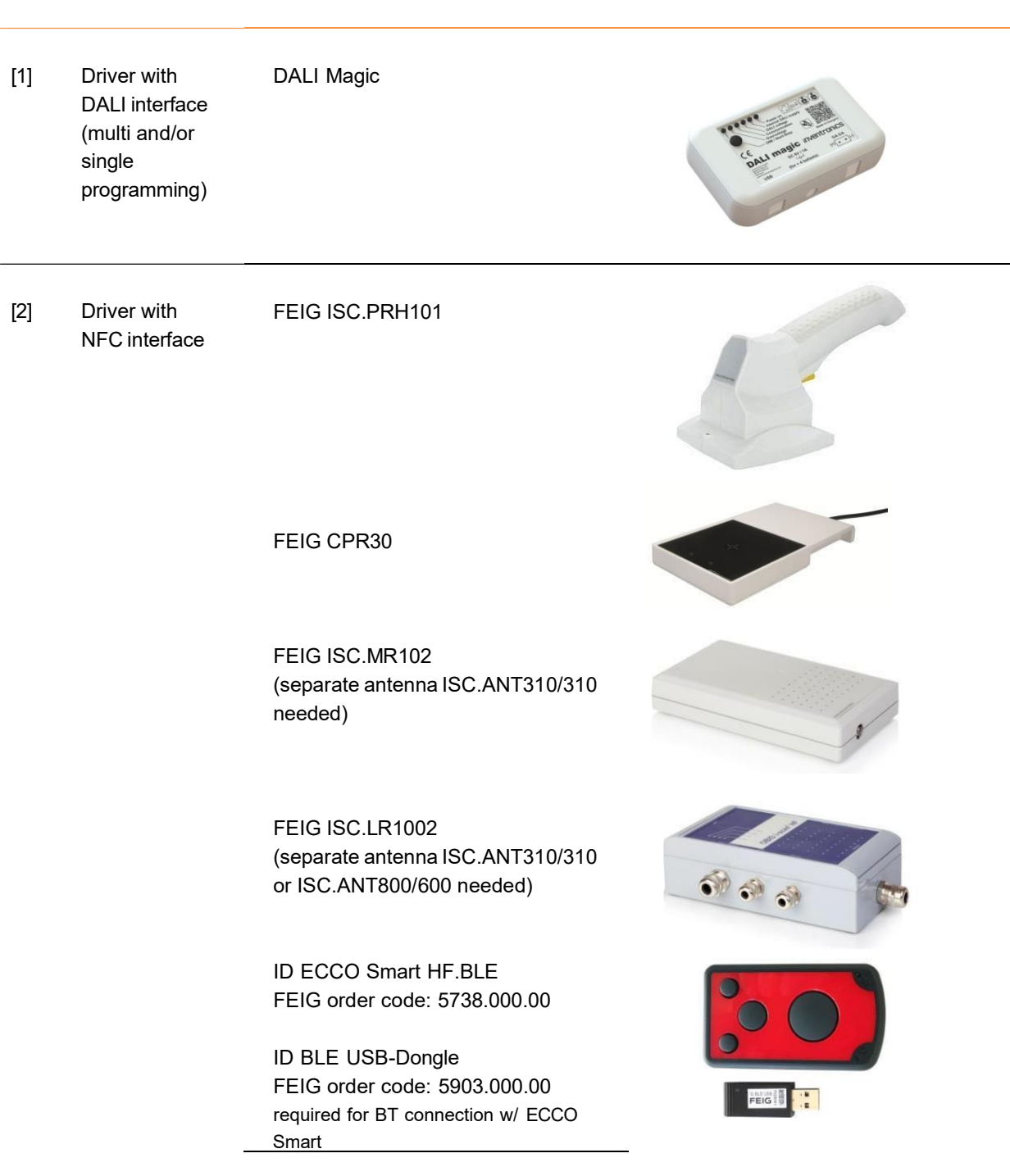
1.5 Programming interfaces
Use an interface suitable for the driver to be programmed.
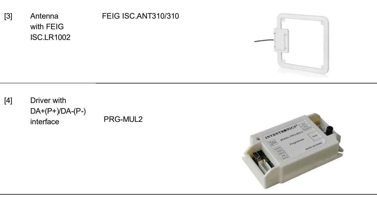
| Driver interface | Programming hardware |
|---|---|
| DALI | DALI Magic for single and/or multiple programming. |
| NFC | FEIG ISC.PRH101, CPR30, ISC.MR102, ISC.LR1002 or ID ECCO Smart HF.BLE. |
| DA+(P+)/DA-(P-) | PRG-MUL2. |
The ISC.MR102 requires a separate ISC.ANT310/310 antenna. The ISC.LR1002 requires a separate ISC.ANT310/310 or ISC.ANT800/600 antenna.
The ID ECCO Smart HF.BLE has FEIG order code 5738.000.00. Its Bluetooth connection requires the ID BLE USB-Dongle, FEIG order code 5903.000.00.
T4T Production can handle more than one programming interface connected to the same PC.
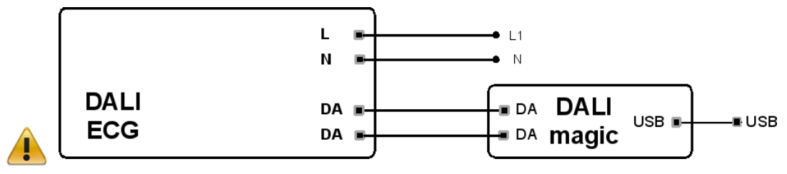
1.6 Prepare a driver with a DALI interface
- Connect DALI Magic to the PC with the supplied USB cable.
- Connect its external 6 V DC power supply. This is mandatory with more than four drivers on the DALI line and is strongly recommended in all cases for communication stability.
- Connect the driver to mains and protective earth (PE), if the driver has a PE terminal.
- Connect DALI Magic's DALI terminals to the driver's DALI inputs.
Most DALI LED drivers allow programming with a low-voltage supply, such as 48 V, instead of mains voltage. Consult the driver's datasheet for details.
1.7 Prepare a driver with an NFC interface
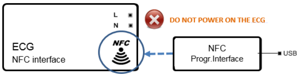
- Connect the NFC reader to the PC with the supplied USB cable.
- Place the driver's NFC area, identified by the logo on the driver, close to the NFC reader.
Important: Keep the driver powered OFF during NFC programming unless its documentation states otherwise. Keep the NFC reader and driver in close contact throughout programming.
1.8 Prepare a driver with a Prog+/Prog- interface
- Connect the OT Programmer to the PC with a USB cable.
- Connect its + and - terminals to the driver's corresponding Prog+ and Prog- terminals or cables.
Warning: Do not power on the driver. Programming through Prog+ and Prog- is not permitted while mains is connected to terminals L/N.
1.9 Prepare a driver with a DA+(P+)/DA-(P-) interface
- Connect PRG-MUL2 to the PC with a USB cable.
- Connect DA-(P-) to Return (grey), DA+(P+) to Programming (purple), and Vaux/Aux+ to Vaux (black/white).
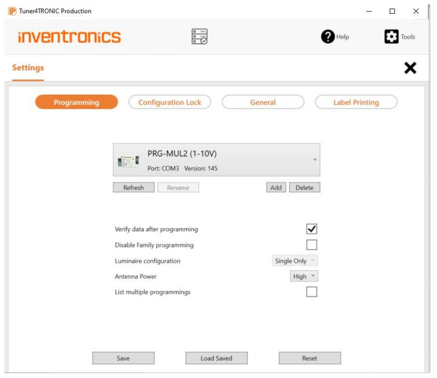
- Open T4T-P4.x, then Tools > Settings > Programming.
- If PRG-MUL2 has already been added, select it from the drop-down list.
To register a new PRG-MUL2:
- Open Add > Add Serial.
- Click Detect.
- Select the correct COM port, for example
COM3: Inventronics PRG-MUL2, v145. - Confirm with Add.
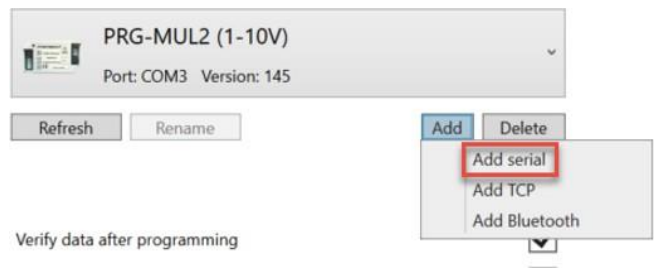
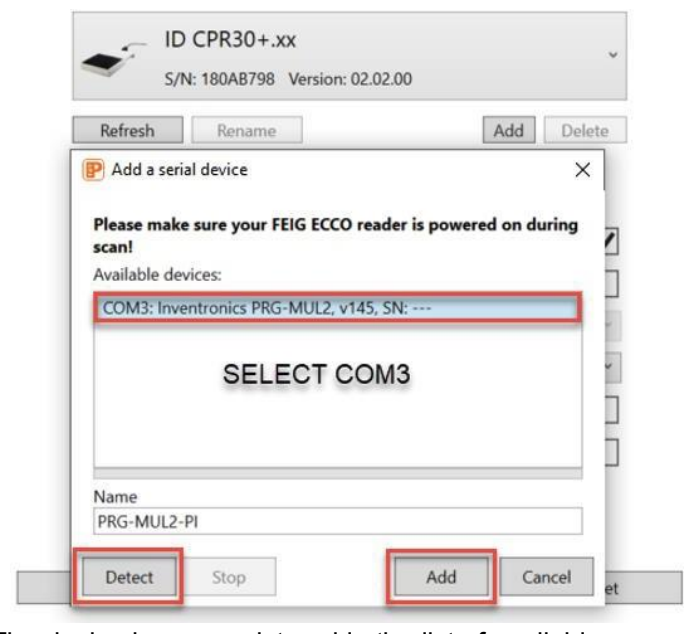
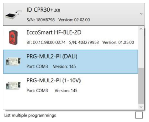
The device is now registered in the list of programmers. Select the mode appropriate to the programming method: PRG-MUL2-PI (DALI) or PRG-MUL2-PI (1–10V).
Warning: Do not power on the driver. Programming through this connection is not permitted while the driver is supplied with mains.
1.10 Software installation
Windows administrator rights are required.
- Extract the Tuner4TRONIC ZIP file to a local folder with a short path, such as
C:\temp. - Run
Install T4T.exefrom that folder. Running the installer from inside the ZIP file causes a faulty installation. - Launch T4T Production from Start > Tuner4TRONIC 4, or double-click its desktop icon.
2 Using T4T Production
2.1 Start page
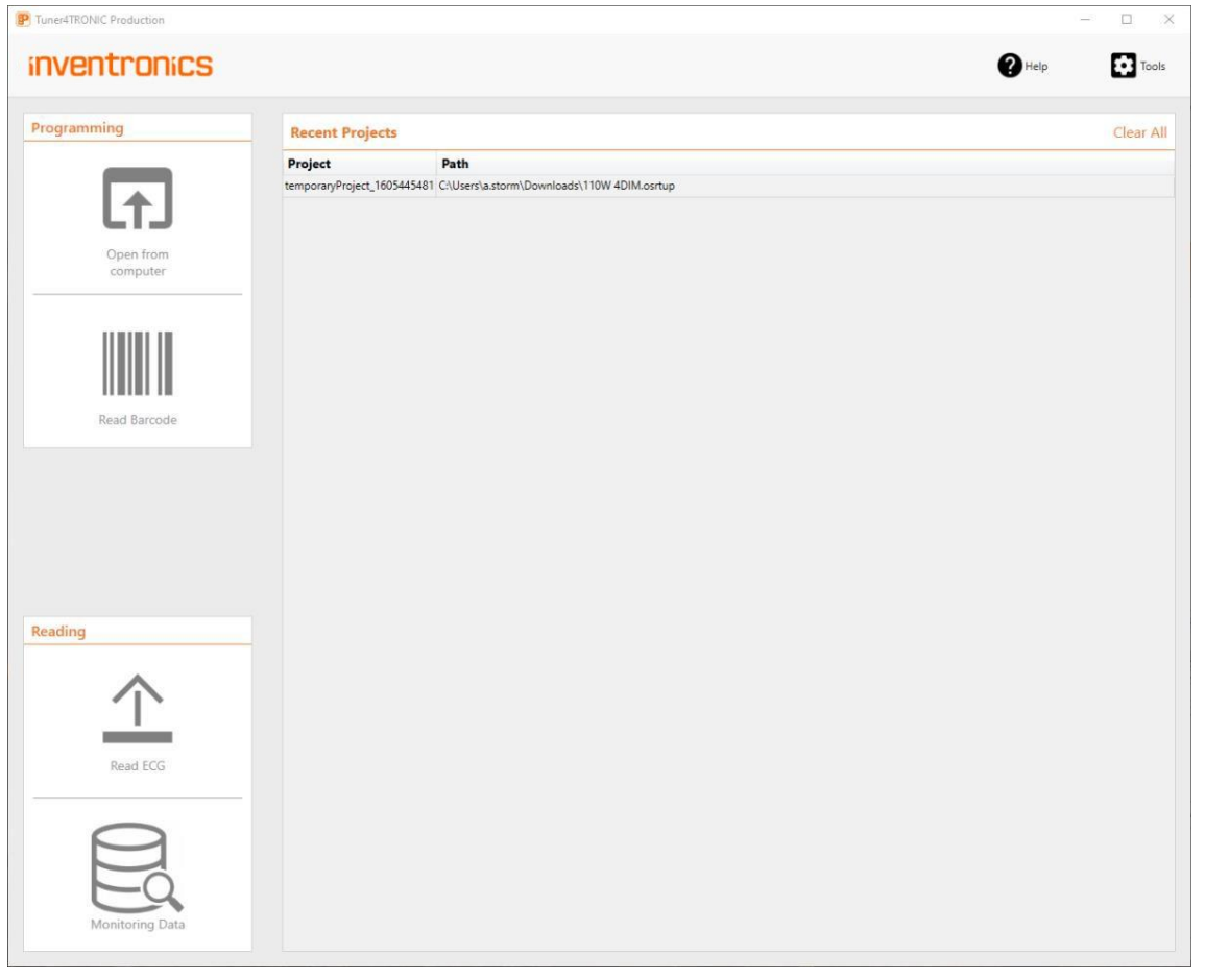
| Control | Function |
|---|---|
| Open from computer | Load an existing .osrtup Production File created by Tuner4TRONIC Cloud, API or Development. The application then opens the Programming page. |
| Read Barcode | Load a Production File from a barcode. |
| Read ECG | Read data from a driver connected through a programming interface. |
| Monitoring Data | Read and display driver monitoring data (PMD, D4i). |
| Recent Projects | Double-click a recently opened project to load it. Clear the list with Clear All. |
| Tools | Open the tools page. |
| Help | Open help and about pages. |
2.2 Programming page
Select Programming on the navigation bar to program devices.
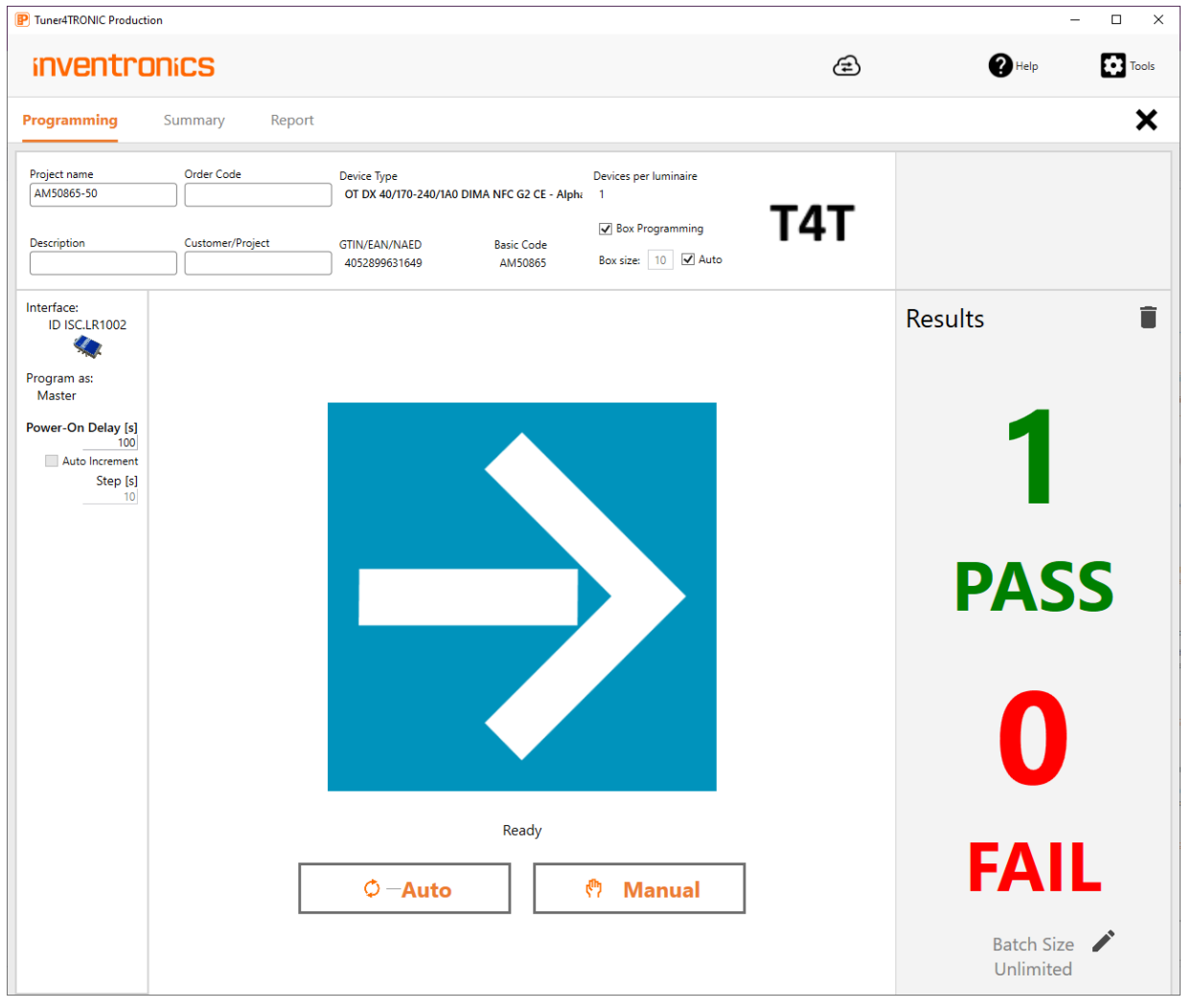
| Area | Function |
|---|---|
| Project Data | Display and edit project data loaded from the Production File. |
| Devices per Luminaire | Display the number of devices in the luminaire from the Production File. |
| Detected Devices | Display the number of detected drivers after a programming button is pressed. |
| Interface | Display the connected programming interface. |
| Status | Show a status symbol, completion bar and text message. |
| Results | Display passed and failed programming events. |
Box programming
Select Box Programming to program drivers in a box via NFC. This requires a suitable programming interface. If the driver is released for box programming, the Auto checkbox fills in the number of drivers by default. The default is loaded from the Production File and can be edited. Programming starts only when the detected number matches the target number.
If verification fails for one or more drivers, all drivers in the box are marked as failed. Program the whole box again. Reprogramming drivers with the same Production File overwrites their report entries without increasing the total number of passes.
Start programming and results
- Manual: Program drivers in one luminaire or one box.
- Auto: Start programming when drivers connect to the interface. Continue until the batch size is reached. In box mode, start when the identified driver count matches the box size.
By default, if the same driver is programmed repeatedly, only its latest pass/fail result is counted and logged in the Production File. View the log on the Report tab.
Use the delete icon to clear the report in the Production File and reset the counter. Use the edit icon to change the batch size. The List multiple programming events setting described in section 2.8 changes how repeated programming is counted.
Programming role
Program as displays the role defined in the Production File:
| Role | Access |
|---|---|
| Master | All features, provided the master key matches the target device. |
| Service | Features protected by the service key, provided it matches, and non-protected features. |
| User | Non-protected features only. |
Power-on delay
If enabled in the Production File, Power-On Delay displays the delay in seconds. Edit the value to override it. Select Auto Increment and enter a step size in seconds to increase the delay after each programming operation. Auto Increment is unavailable with box programming.
Additional DALI options
Single-driver programming: With DALI Magic selected, program one connected driver compatible with the Production File, or read data from any single driver. If the driver differs from the Production File, T4T-P uses the online or offline family programming service. DALI addressing follows the file's settings: keep the address when addressing is disabled, unassign it, or assign a new address.
Batch programming: With multiple drivers on the DALI line, program all compatible drivers using family programming. DALI addresses are deleted after programming. Production Files with DALI Addressing enabled are rejected for batch programming.
Selective programming: Enable Selective Programming to program specific drivers identified by DALI short addresses. Click Search to scan the installation. Compatible drivers are highlighted in green; select their checkboxes. Select blink to identify a luminaire physically.
Enter short addresses separated by commas; ranges such as 2-9 are also accepted. The DALI bus is scanned before programming to avoid duplicate addresses.
Selective programming is rejected for drivers in multi-channel operating mode. It cannot switch the operating mode of multi-channel drivers; use NFC or connect a single driver instead.
Online services
The cloud icon indicates that online services are connected. These services automatically update device description files with the latest drivers from DD-store and notify users of T4T-P updates.
Programming status indicators
| Status | Meaning and action |
|---|---|
| Waiting for Luminaire | Connect a luminaire or drivers to start or continue programming. |
| Programming in progress | Do not remove the connected luminaire or drivers until programming completes. |
| PASS | Programming completed successfully. Remove the luminaire or drivers. |
| FAIL | Programming stopped because of user action or an error. Read the on-screen message, fix the problem and restart. |
2.3 Summary page
Select Summary to display the Production File's parameters.
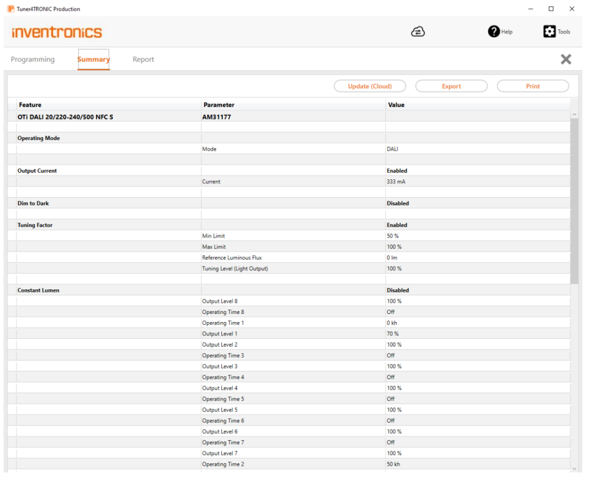
| Control | Function |
|---|---|
| Update (Cloud) | Use cloud services to convert report values into clear text when the Production File does not include a clear-text report. |
| Export | Create an HTML file containing the parameters. |
| Print the parameter list. |
2.4 Report page
Select Report to display the programming report.
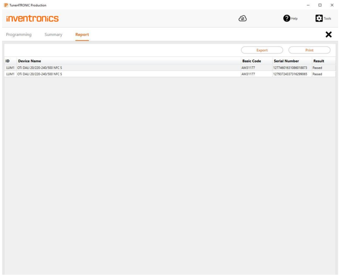
Export creates an HTML report with one line for each driver, luminaire or box programming result. Print prints the report.
2.5 Read ECG
Click Read ECG on the start page to read a driver through NFC, DALI or an OT Programmer. With DALI Magic selected, enter a DALI short address to select a specific driver on the network.
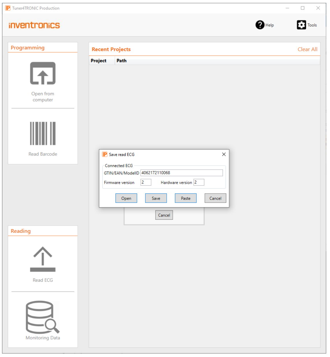
| Option | Function |
|---|---|
| Open | Open T4T Configurator in a new tab in the default browser and create a project using the driver data. |
| Save | Save driver data locally as an .osrtur readback file. Import it into T4T Configurator to display data and create Production Files. This is useful while T4T-P4 is offline. |
| Paste | Create a new Production File from the driver data and import it into T4T-P4 to clone settings, for example when replacing a driver. Requires internet access to cloud services. |
Passwords are not retrieved in plain text. The encrypted master password indicates that the driver is protected; passwords must be re-entered when creating a Production File in Configurator. The Paste workflow includes a password in the new Production File, hidden from the user, to unlock and protect the new drivers.
2.6 Monitoring data
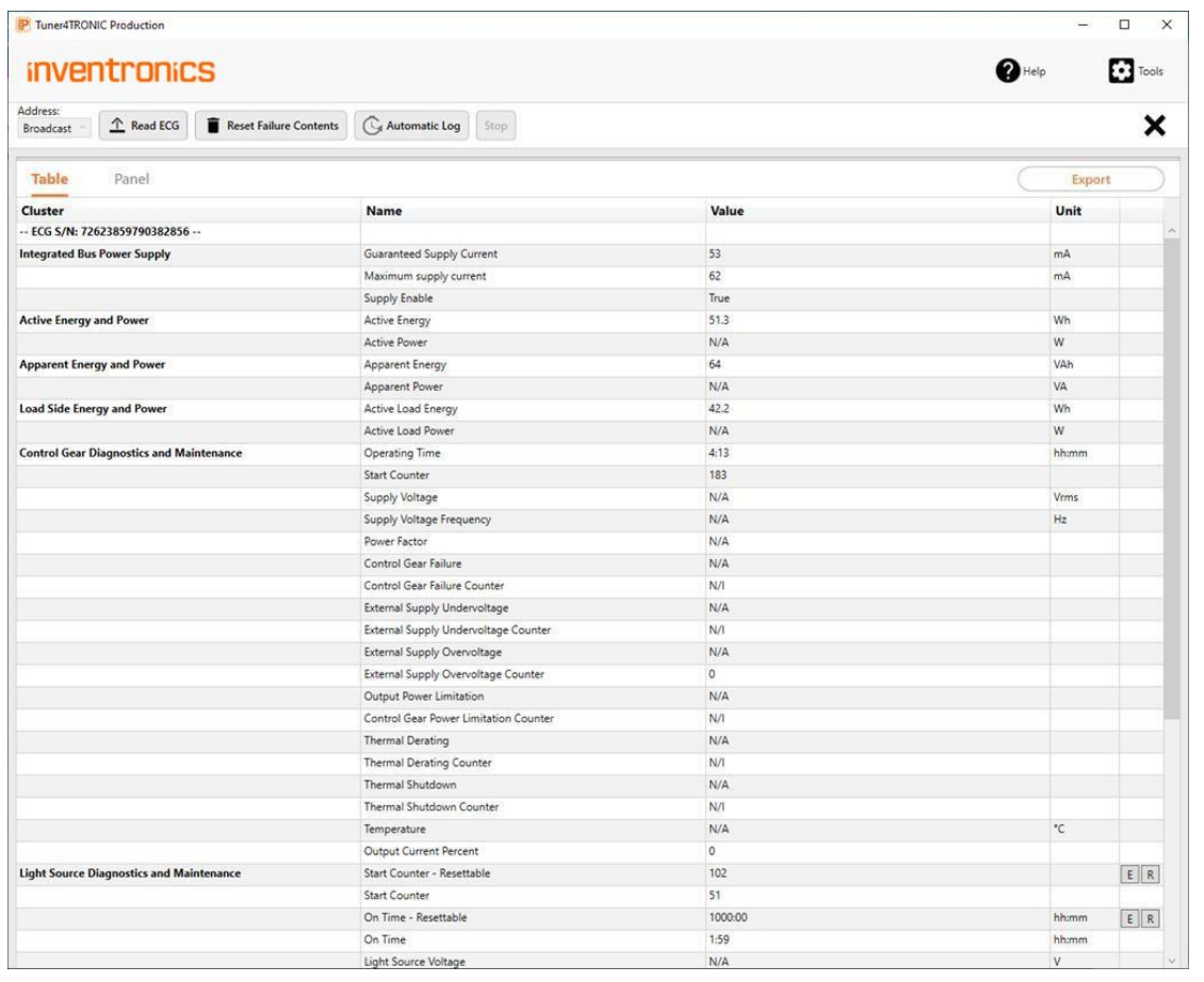
| Control | Function |
|---|---|
| Address | With DALI Magic, use broadcast only when exactly one driver is connected. If several drivers are connected, select one by its DALI short address. |
| Read ECG | Read monitoring data through the selected programming interface. |
| Resettables | Press E to edit values or R/the reset control to reset them. Changes take effect after the next driver power-on. |
| Automatic Log | Repeatedly read monitoring data and log it. |
| Stop | Stop reading monitoring data. |
| Table | Display a table view. |
| Panel | Display a panel view. |
| Export | Create an HTML file containing the parameters. |
The appendix lists Monitoring Data v2 parameters and identifies those available only through DALI.
2.7 Tools page
Click Tools and select an entry from the drop-down menu.
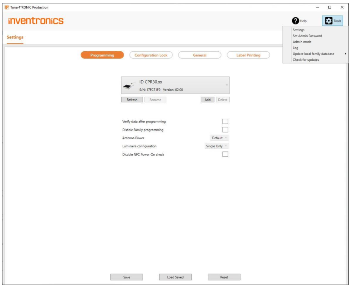
| Entry | Function |
|---|---|
| Settings | Open the settings pages described below. |
| Set Admin Password | Enter or delete the password for admin mode. |
| Admin Mode | Toggle admin mode. The source manual states that, when activated, the Production File cannot be reloaded and project data cannot be edited. |
| Log | Display debugging logs. Right-click the log window to export a CSV log file. |
| Update local family database | Update the family programming database from the cloud or a local ZIP file when offline. Download the ZIP from Software Downloads on the Inventronics Tuner4TRONIC page. |
| Check for Updates | Check the download center for new T4T-P versions. Updates affect T4T-P4 and T4T-S simultaneously. |
2.8 Settings - Programming
Open Tools > Settings > Programming.
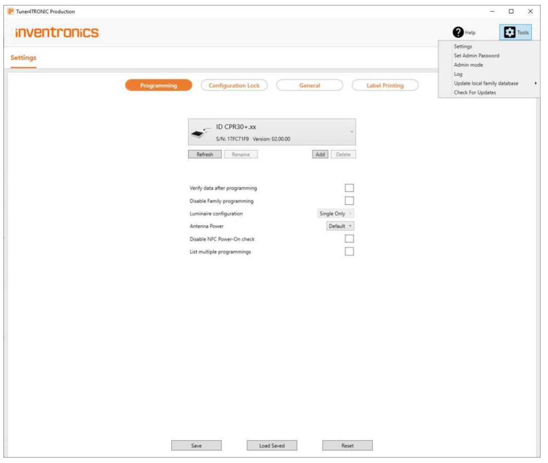
Save, Load Saved and Reset
- Save: Save options locally and in the Production File where applicable. Unsaved changes are ignored when T4T-P restarts.
- Load Saved: Load options from the local computer and Production File where applicable.
- Reset: Restore factory settings and data from the Production File where applicable.
Select a programming interface
Select an interface from the drop-down list. Ensure that it is connected and not used by another tool. Click Refresh to refresh the USB interface list.
For interfaces using a COM port, such as OT Programmer, FEIG ECCO with a Bluetooth dongle or PRG-MUL2, click Add Serial, then Detect. Select a device, assign a name and click Add.
For TCP/IP interfaces, such as LR1002, click Add TCP, enter the IP address and click Detect. Added interfaces remain in the list after restarting the application.
Verify data after programming
Enable automatic verification after every programming operation. The default comes from the Production File.
Disable family programming
Family programming allows a Production File to program drivers in the same family and drivers of the next generation. It does not support previous generations.
Select Disable Family programming to reject every driver other than the one specified in the Production File. The default comes from that file.
Family programming uses cloud services. Without internet access, or with cloud services disabled, it uses the service installed locally with T4T-P4. Keep the local database current using the update entry in Tools.
Antenna power
Adjust antenna power to the setup. The source manual notes that FEIG CPR30+ supports higher antenna power for drivers with weak NFC antennas.
Luminaire configuration
Select single or multiple programming. Multiple programming supports several DALI-connected drivers, such as a test rack or a luminaire with multiple drivers. The default comes from the Production File.
Disable NFC Power-On check
Normally T4T-P4 rejects NFC programming while the driver is connected to mains because NFC data may be corrupted. In the worst case, programming can be acknowledged even when data was not programmed correctly. Drivers use a power-on flag in their NFC tags to indicate that they are powered.
The source manual describes production lots where this flag was set incorrectly despite the driver being disconnected from mains. Disabling the check allows these drivers to be repaired by programming.
Warning: Before disabling the NFC power-on check, ensure that the driver is not powered. The software will not perform this check. Do not disable it by default.
List multiple programming events
By default, programming the same driver, identified by its serial number, twice overwrites its previous event without increasing the counter. Enable List multiple programming events to count every programming operation and retain all events with separate timestamps.
2.9 Settings - Configuration Lock
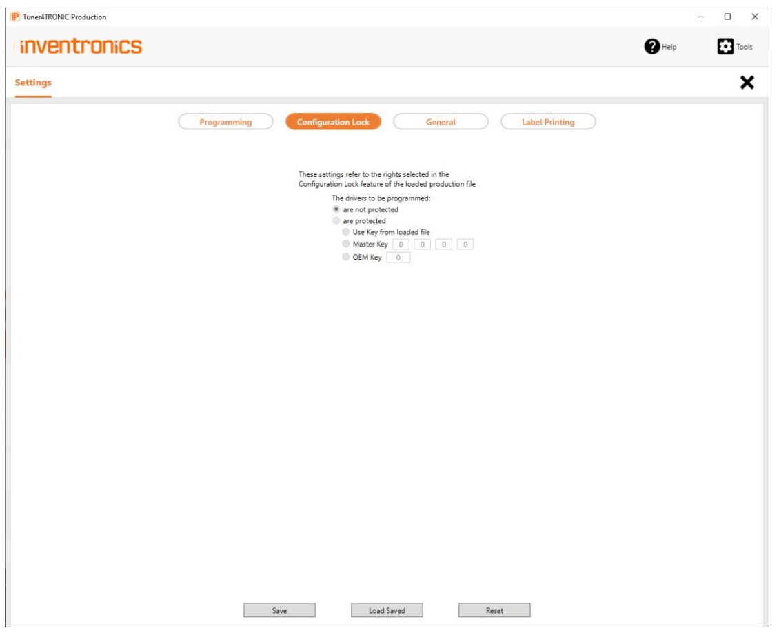
Open Tools > Settings > Configuration Lock to override password settings from the Production File and allow programming of protected drivers. Use Master Key for drivers with two-level password protection, or OEM key for single-level password protection.
2.10 Settings - General
Open Tools > Settings > General to edit general parameters.
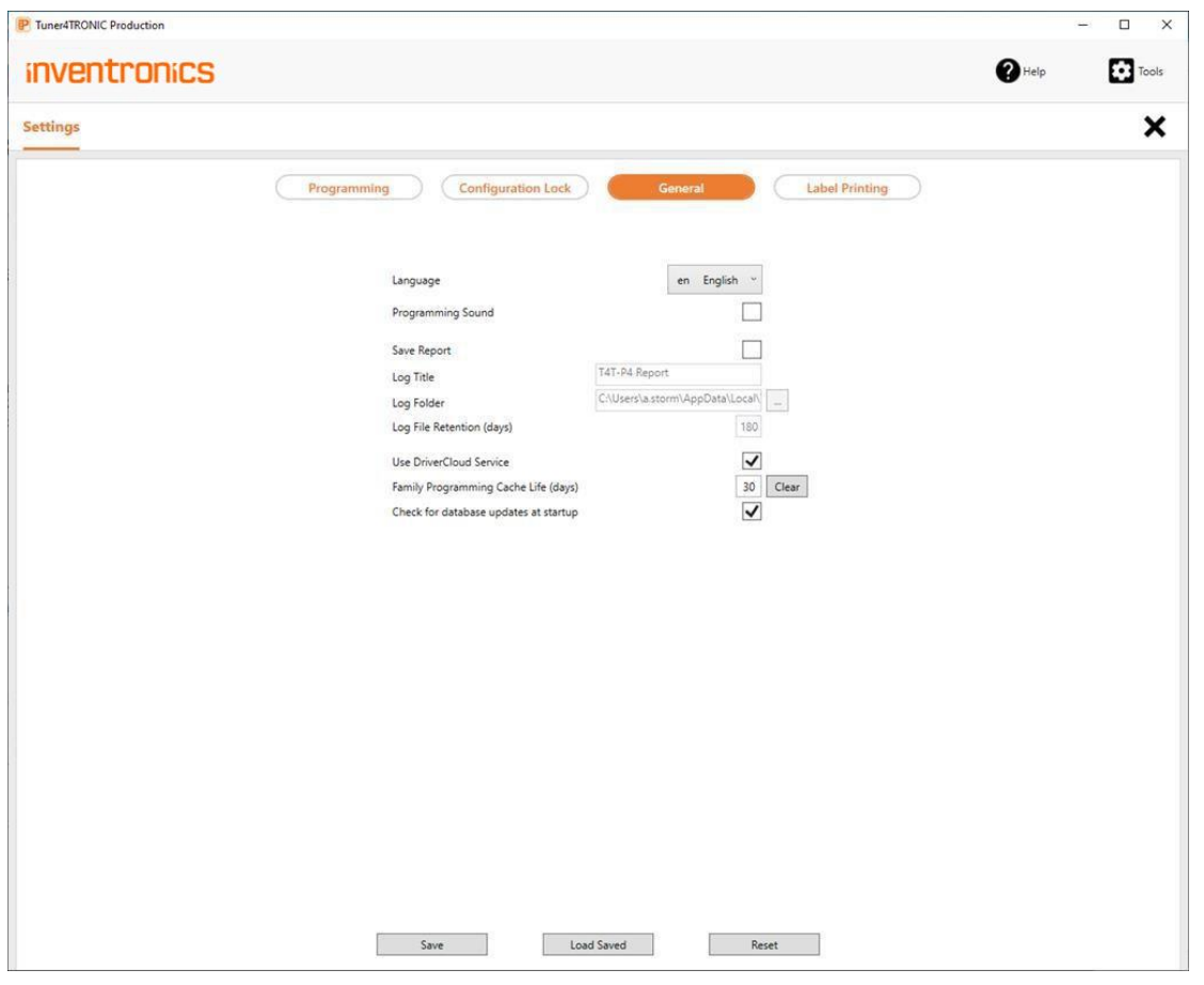
| Setting | Function |
|---|---|
| Programming sound | Play a sound after each programming operation. |
| Logging | Create HTML programming logs using the configured title and folder. |
| Log Files Retention (days) | Delete expired logs to free local storage. |
| Cloud Service | Enable family programming, automatic offline family database updates, T4T update notifications, clear-text reports and the driver registry. |
| Family programming cache | Delete cached family programming files after the retention period to free storage. |
| Check for database updates at startup | Check for database updates whenever T4T-P starts. |
2.11 Settings - Label Printing
T4T Production can automatically trigger label printing after each driver is programmed. Labels can include luminaire information, barcodes or QR codes for later identification. Two methods are supported: CSV label printing and Zebra direct printing.
CSV label printing
T4T Production exports the data; third-party software designs and prints the labels. Use an automation-capable edition of label software such as NiceLabel or BarTender to create the template, including barcodes or QR codes, and trigger printing. Label definition templates use .nlbl files.
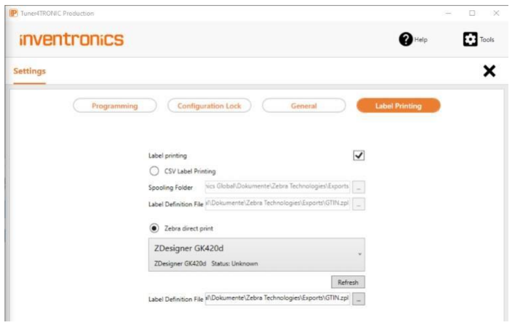
- Open Tools > Settings > Label Printing and enable label printing.
- Select CSV Label Printing and browse for the label definition file and spooling folder.
- Configure the third-party application to monitor the spooling folder and combine new driver data with the label template.
After each successful driver programming, T4T creates Output.csv in the spooling folder. It contains the parameters written into the driver, such as operating current, dimming, luminaire name and information, individual serial number and GTIN.
Output.csv contains only the latest driver's data and is overwritten after each programming operation. The monitoring label application triggers printing automatically when the file is created. With box programming, one label is created per driver, for example 20 labels for a box of 20 drivers.
Zebra direct print
T4T can inject data into ZPL templates and send labels directly to Zebra printers without third-party printing software. Create a ZPL template with a design tool such as ZebraDesigner 3.
To insert driver or project data, enclose the property name in curly brackets, for example {GTIN}. Available properties appear in the Label Definition section.
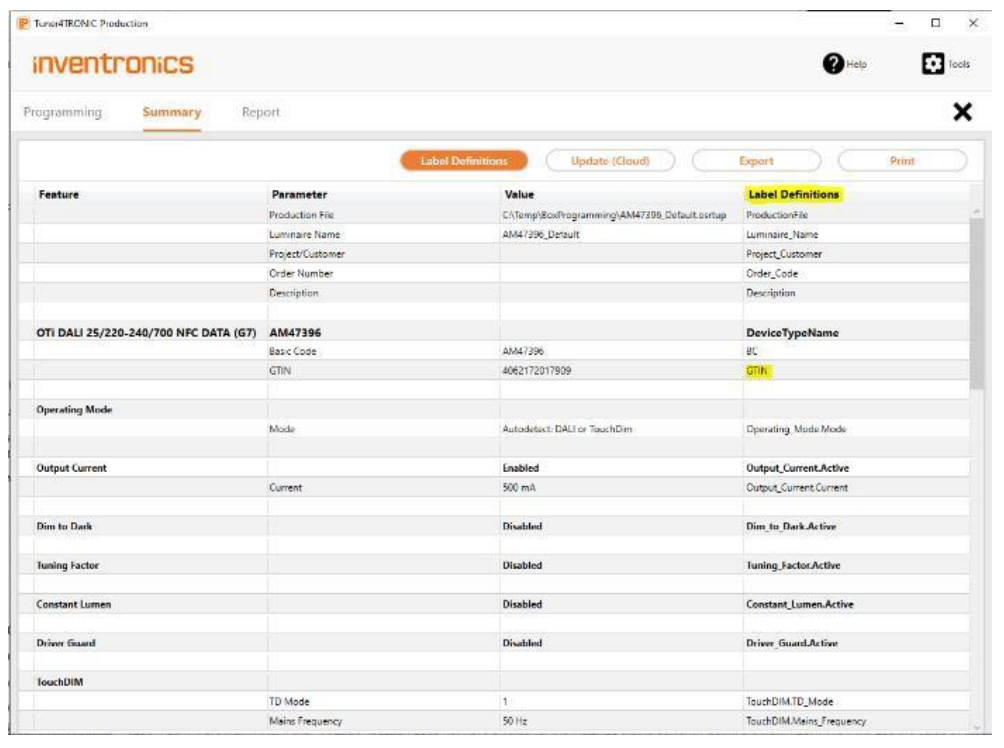
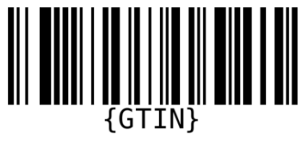
Sample ZPL file:
^XA
^BY5,2,170
^FO100,50^BC^FD{GTIN}^FS
^XZ
Appendix - Monitoring Data v2
The following tables preserve the parameter groups and descriptions from the source manual. An asterisk (*) means the parameter can only be read through DALI. Reading monitoring data through NFC does not provide every parameter, such as power.
Energy
| Group | Parameter | Description |
|---|---|---|
| Active Energy & Power | Active Energy | Integral of instantaneous power over time, in watt-hours. |
| Active Energy & Power | Power* | Under periodic conditions, mean instantaneous power over one period, in watts. |
| Apparent Energy & Power | Apparent Energy | Integral of apparent power over time, in volt-ampere-hours. |
| Apparent Energy & Power | Apparent Power* | Product of RMS terminal voltage and RMS current. |
| Load Side Energy & Power | Active Energy Loadside | Integral of load-side power over time, in watt-hours. |
| Load Side Energy & Power | Active Power Loadside* | Input power minus DALI bus supply power and auxiliary supply power, where present. Supply losses may be neglected in the measurement. |
Driver diagnostics and maintenance
| Parameter | Description |
|---|---|
| Operating Time | Control gear powered operating time in seconds, regardless of the lampOn bit. |
| Start Counter | Number of control gear starts caused by external supply power cycles. A power cycle is counted when power-on time is at least 600 ms. |
| External Supply Voltage* | RMS external supply voltage. |
| External Supply Voltage Frequency* | External supply frequency. A value of 0 indicates pure DC or rectified AC; examples: 17 for 16.7 Hz and 50 for 50 Hz. |
| Power Factor* | A ControlGearPowerFactor value of 100 means a power factor of 1.00. |
| Overall Failure Condition* | Indicates whether the LED driver has experienced a failure. |
| OverallFailureConditionCounter | Number of overall failure conditions. |
| External Supply Undervoltage* | Indicates supply voltage below the specified input range. |
| ExternalSupplyUndervoltageCounter | Number of external supply undervoltage events. |
| External Supply Overvoltage* | Indicates supply voltage above the specified input range. |
| ExternalSupplyOvervoltageCounter | Number of external supply overvoltage events. |
| Output Power Limitation* | Indicates driver output power above the output power limit. |
| OutputPowerLimitationCounter | Number of output power limitation events. |
| Thermal Derating* | Indicates output current reduction because driver temperature reached a level that could affect lifetime or performance. |
| ThermalDeratingCounter | Number of thermal derating events. |
| Thermal Shutdown* | Indicates output current reduced to zero because driver temperature exceeded the thermal shutdown threshold, above the derating threshold. |
| ThermalShutdownCounter | Number of thermal shutdowns. |
| Temperature (internal)* | Internal control gear temperature encoding: a value of 60 means 0 °C; 0 means -60 °C. |
| Output Current Percent* | Driver output current as a percentage of nominal current, including internal reductions except those due to constant lumen functionality. |
Lamp diagnostics and maintenance
| Parameter | Description |
|---|---|
| StartCounterResettable | Resettable count of light-source starts. |
| Start Counter (Total) | Total light-source starts. |
| On Time Resettable (CLO) | Light-source operating time in seconds. The CLO profile follows this value; it can be reset or edited to any value. |
| On Time (Total) | Total light-source operating time in seconds. |
| Output Voltage* | Actual driver output voltage. |
| Output Current* | Actual driver output current. |
| Overall Failure Condition ("Lamp failure") | Indicates whether the luminaire has experienced a failure. |
| Overall Failure Condition Counter | Number of lamp failures. |
| Short Circuit | Indicates a lamp failure with a short circuit. |
| Short Circuit Counter | Number of lamp short circuits. |
| Open Circuit | Indicates a lamp failure with an open circuit. |
| Open Circuit Counter | Number of lamp open circuits. |
| Thermal Derating | Indicates output current reduction because lamp temperature reached a level that could affect lifetime or performance. |
| Thermal Derating Counter | Number of lamp thermal derating events. |
| Thermal Shutdown* | Indicates output current reduced to zero because lamp temperature exceeded the thermal shutdown threshold, above the derating threshold. |
| Thermal Shutdown Counter | Number of lamp thermal shutdowns. |
| Temperature* | Light-source temperature encoding: 60 means 0 °C; 0 means -60 °C. Measured by an external sensor thermally coupled to the light source; the sensor interface and configuration are manufacturer-specific. |
Service contact
Inventronics GmbH
Parkring 31-33
85748 Garching, Germany
Phone: +49 89 6213-0
www.inventronicsglobal.com
Tuner4TRONIC support: T4Tsupport@inventronicsglobal.com