
Tunable White LED systems with constant-current drivers
Technical application guide covering Tunable White fundamentals, LED modules and drivers, Tuner4TRONIC configuration, wiring, thermal design, and mounting.
Updated · by Administrator
On this page
- Contents
- Please note
- 1 Introduction
- 2 Physical and technical background and basics
- 2.1 Color space
- 2.2 Color mixing in the color space
- 2.3 Melanopic effect
- Spectral sensitivity
- 2.4 Temperature and current dependency of color coordinates and efficacy of LEDs
- Basic Mode
- Advanced Mode
- Premium Mode
- 2.5 Easy color and brightness control for floor-standing luminaires: Touch DIM TW
- Diode
- General wiring of the TW driver with Inventronics TW modules
- Typical applications of floor-standing luminaires
- Secondary-side wiring of the TW modules
- 3 System components
- 3.1 TW modules
- 3.2 Technical features of Inventronics TW drivers
- 3.3 Configuration tool Tuner4TRONIC® (T4T)
- Please note
- 3.3.1.2 Create or edit new TW modules
- 3.3.1.2.1 Input data for data model “Basic Mode”
- 3.3.1.2.2 Data entry for the “Advanced Mode”
- 3.3.1.2.3 Input data for data model “Premium Mode”
- 3.3.2 Configuration of TW drivers
- 3.3.2.1 Adjustment of 100 % operating current and balancing with TW module
- 3.3.2.2 Additional DALI settings for LED drivers supporting Tunable White
- 3.3.2.3 DALI TW settings
- 3.3.2.4 Driver operation in single-color operation modes
- 3.4 Light management systems (LMS)
- Product benefits
- Areas of application
- Equipment/accessories
- Functionality/operation
- Areas of application
- DALI Pro Control app
- The app features at a glance
- Product features
- Product benefits
- Equipment/Accessories
- Energy Monitoring and Maintenance Assistant
- Product features
- Product benefits
- Equipment/Accessories
- References/Links
- 4 Handling
- 4.1 Wiring
- 4.2 Release connections
- 4.3 Electrostatic discharge (ESD)
- 4.4 NFC programming
- 4.5 Exemplary assembly of a five-foot TW luminaire with 5500 lm
- Example for interconnection with non-isolated modules
- Non-isolated module 3 (280 mm)
- Series connection of the three modules
- Example for interconnection with 700 mA SELV modules
- SELV module 3 (280 mm) 700 mA LV
- Series connection of the three modules
- Example for interconnection with 1A4 SELV modules
- SELV modules 1 and 2 (560 mm) 1,400 mA LV
- SELV module 3 (280 mm) 1,400 mA LV
- Series connection of the three modules
- 5 Thermal considerations
- 6 Mechanical considerations
- Disclaimer
- Service contact
Tunable White LED systems with constant-current drivers

Technical application guide · Inventronics · October 2023
This guide covers dynamic Tunable White systems, their technical background, system components, configuration with Tuner4TRONIC, and electrical, thermal, and mechanical integration.
Source edition: October 2023. Product names, software screens, specifications, and contact details are retained from that edition.
Contents
- 1 Introduction
- 2 Physical and technical background and basics
- 3 System components
- 4 Handling
- 5 Thermal considerations
- 6 Mechanical considerations
- Disclaimer
Please note
All information in this guide has been prepared with great care. Inventronics, however, does not accept liability for possible errors, changes and/or omissions. Please check www.inventronics-light.com or contact your sales partner for an updated copy of this guide. This technical application guide is for information purposes only and aims to support you in tackling the challenges and taking full advantage of all opportunities the technology has to offer. Please note that this guide is based on own measurements, tests, specific parameters and assumptions. Individual applications may not be covered and need different handling. Responsibility and testing obligations remain with the luminaire manufacturer/ OEM/application planner.
1 Introduction
1.1 Content and intention
This application guide for dynamic Tunable White LED systems with constant-current and constant-voltage drivers as well as modules informs about technical basics of light and necessary system components and configurations.
TW systems enable the creation of “white light” within a bandwidth of two different color temperatures by using LED modules equipped with LEDs that have two different color temperatures.
TW systems provide basic technical components for Human Centric Lighting (HCL) solutions. The usage of such components and systems enables the creation of biologically effective white light in terms of dynamic brightness and variable color temperature settings.
Targeted Human Centric Lighting solutions are the result of tailor-made lighting planning and create a balance between visual comfort, emotional perception and biological effects.
Human Centric Lighting provides targeted and long-term support for health maintenance, well-being and efficiency of human beings through holistic planning and consideration of visual, emotional and especially biological effects of light. Each human being with his or her needs concerning life, work and leisure is consistently placed in the focus of attention. The interdisciplinary balance between the parameters of artificial lighting, natural daylight, architecture and technology creates the right light at the right time.
Together with leading luminaire manufacturers, we develop tailor-made Human Centric Lighting concepts based on scientific expertise and with consideration of the set of standards for indoor lighting. We hereby support the luminaire manufacturers to enable Human Centric Lighting solutions. You can find more information here: www.inventronics-light.com/hcl
2 Physical and technical background and basics
2.1 Color space
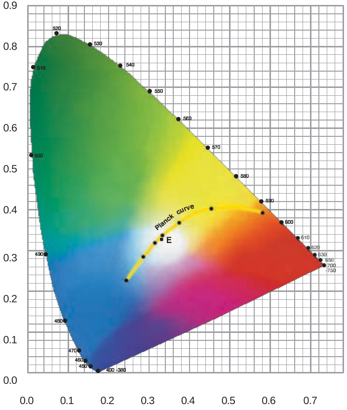
The color space visualizes all visible colors that a human eye can perceive. Color locations that lie on the Planck curve are designated as white light. This curve is characterized by the fact that the color temperature corresponds to the light emission of a solid body at the respective temperature. Color locations outside of the Planck curve can also be referred to as white light; constant color temperatures are located on the Judd straight lines. Color locations which are more than approx. 10 threshold units away from the Planck curve are usually not considered to be white light.
2.2 Color mixing in the color space
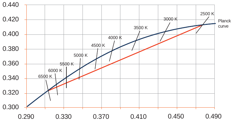
LED modules providing light with adjustable color temperature are equipped with LEDs that have two different color temperatures. The adjustable color locations are addressable by supplying suitable current levels to the respective LEDs.
Principally, only color locations that lie on the connecting line between both LED color locations can be addressed.
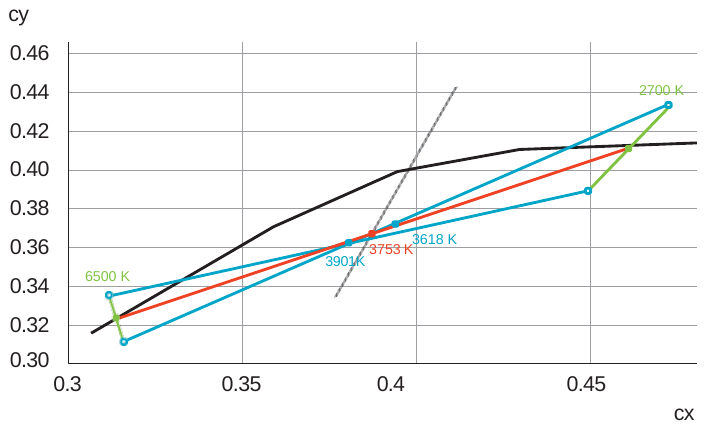
It should be considered that the color coordinates of LEDs do not necessarily lie on the Planck curve.
The deviation between the cx/cy coordinates of the applied LEDs and the intersection of the Judd line with the Planck curve can lead to color coordinates of the mixed light that differ significantly from a desired target color location.
The following picture exemplarily shows that the color temperature of the mixed light depends on the actual color coordinates of the LEDs, although their nominal color temperature and forward current are the same.
2.3 Melanopic effect
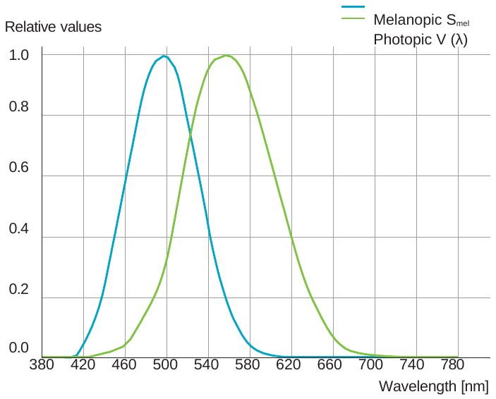
The melanopic effect determines the circadian effect of a light source and influences the wellness of human beings. The melanopic values describe how strong the melanopin-containing retinal ganglion cells (ipRGC) are stimulated by light. In analogy to the definition of the V (λ) curve for the spectral sensitivity of the photoreceptor cells, Smel (λ), which expresses the spectral sensitivity for these photoreceptors, was defined.
According to this, the melanopic luminous flux describes the radiant flux of a light source, evaluated with the spectral sensitivity of the melanopic (non-visual) photoreceptors.
The melanopic factor describes the ratio between the melanopic and the photometrically effective amount of radiation. This factor is higher when a light spectrum stimulates the non-visual system more strongly.
Daylight-equivalent values practically represent a benchmark with reference to natural daylight.
Thus, the melanopic daylight-equivalent luminous flux related to 1000 lm indicates how many lumen of daylight are needed to achieve an equally large non-visual stimulation as with the mentioned artificial light.
Spectral sensitivity
2.4 Temperature and current dependency of color coordinates and efficacy of LEDs
2.4.1 Typical properties of LEDs
The luminous flux and the color coordinates of an LED are not only subject to manufacturing tolerances, but also depend on its operating conditions.
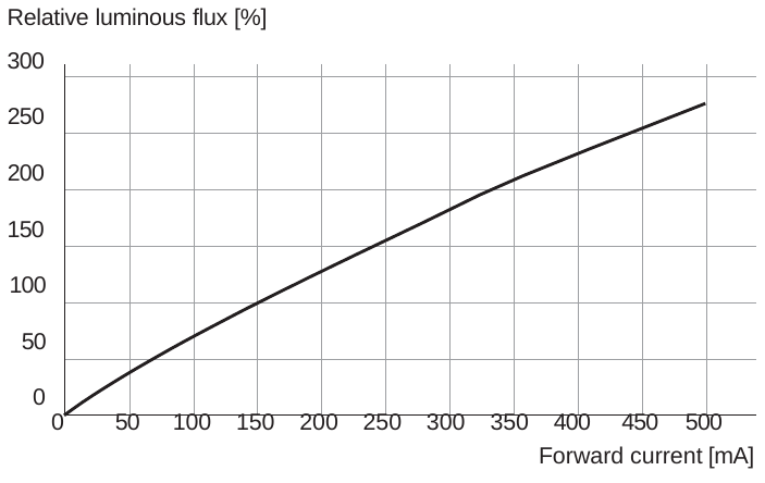
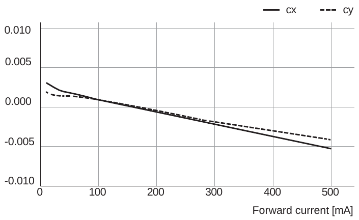
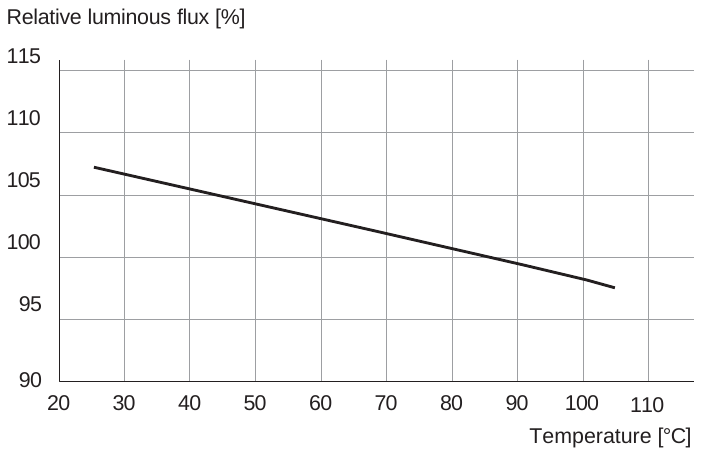
The following pictures show typical curves for the dependency of luminous flux and color locations on forward current or temperature:
Relative luminous flux versus forward current
Color coordinates versus forward current
Relative luminous flux versus temperature
Color coordinates versus temperature
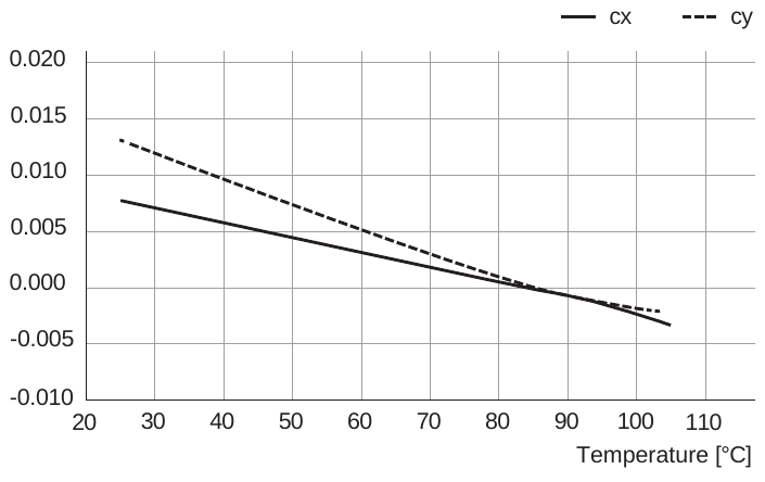
To achieve the best possible match between the desired and the achieved color coordinates of mixed light, non-linear dependencies must be considered when calculating the LED currents.
2.4.2 Data models for LED modules
To match the various requirements with regard to simple operation and high color quality, three data modes for LED modules are available for configuring our TW drivers.
The focus here is on enabling sufficient color accuracies with a simple set-up as well as very good color accuracies by using typical LED and module data.
Basic Mode
In the Basic Mode, the values of the color temperatures of both applied LED types must be entered, e.g. 2700 K and 6500 K. In addition, forward currents must be entered for both channels that lead to luminous flux (100 % values) equity.
The Tuner4TRONIC® (T4T) configuration software transmits these values to the drivers, which then adjust both output currents in dependence of the desired color location following the ratio between the target color location and the two LED color temperatures.
However, this very simple model also shows some disadvantages:
-
Since the color coordinates of LEDs are usually not exactly on the Planck curve, the input of the nominal color temperature already implies deviations, see chapter 2.4.1.
-
A purely proportional setting of the LED currents causes a deviation from the target color location because the connecting line between both LED color locations is only an approximation to the Planck curve. Since the Judd straight lines do not vertically intersect the Planck curve and the connecting line, deviations of up to several 100 K are possible.
-
The dynamic behavior of the LEDs is not considered, which means that resulting color coordinates may shift when the temperature changes, e.g. during dimming, see also chapter 2.4.1.
Advanced Mode
In the Advanced Mode, in addition to the nominal cx and cy coordinates of the LEDs, the data which represent the operating conditions of the LEDs in the projected application must also be entered.
The calculation of the output currents is not carried out only once in relation of the target color coordinates to the nominal color temperature of the applied LEDs, but follows an iterative process. In this process, the currents are iteratively calculated as a function of the specified operating conditions, the color coordinates of the LEDs and simplified LED characteristics.
Advantages of the Advanced Mode include:
-
Entering the real color coordinates of the LEDs instead of the nominal color temperature values eliminates color deviations that already occur due to the deviation of the LED color coordinates from the Planck curve.
-
By performing the iterative calculation process of the output currents of the driver, a higher color accuracy is achieved by considering the positions of the intersections of the Judd lines with the connecting line.
Premium Mode
In the Premium Mode, the output currents of the driver are calculated in the same way as in the Advanced Mode, but real dynamic LED characteristics are used instead of simplified LED characteristics.
As in the Advanced Mode, the operating conditions of the LED module in a projected application must be entered to enable a high color accuracy.
In order to enter the LED characteristics, it is necessary to determine three operating points of a single LED for each criterion using the LED data sheets and to implement them by using the T4T configuration software.
For each type of LED, the following data must be fixed:
-
Three value pairs each for cx and cy coordinates as a function of the forward current
-
Three value pairs for luminous flux as a function of the forward current
-
Three value pairs each for cx and cy coordinates as a function of the LED temperature
-
Three value pairs of luminous flux as a function of the LED temperature
All value pairs to be entered can be selected completely independently from the operating conditions in a projected application, since they only have to reflect the characteristics of the LEDs but not the operating points of the LEDs in an application.
Generally, when our TW modules are used, the Premium Mode is always used. All necessary LED and module data are already stored in the T4T.
If other TW modules freely available on the market are used, the LED data required for the Premium Mode must be obtained.
In addition to the Advanced Mode, the Premium Mode offers the following advantages:
-
When calculating the output currents, the non-linear dependencies of the luminous flux and the color coordinates of the LEDs on forward current and temperature are taken into account.
-
A high color homogeneity is achieved in a system in which the modules are operated under different conditions, e.g. at different dimming levels or ambient temperatures.
-
The absolute color accuracy essentially depends only on the tolerances of the LEDs used in relation to their nominal data. Usually, LEDs with a color tolerance up to three MacAdam steps are available.
2.5 Easy color and brightness control for floor-standing luminaires: Touch DIM TW
The functionality Touch DIM TW allows for the intuitive manual dimming, switching and adjusting of brightness and color temperature via double pushbutton. It is particularly suitable for floor-standing luminaires (with integrated pushbuttons) and similar applications.
To use Touch DIM TW, the Tunable White LED driver has to be configured with the software Tuner4TRONIC® in the operation mode ”Tunable White-Touch DIM“.
The maximum length of the control line is 3 m. Brightness and color are stored by double-clicking the corresponding pushbutton.
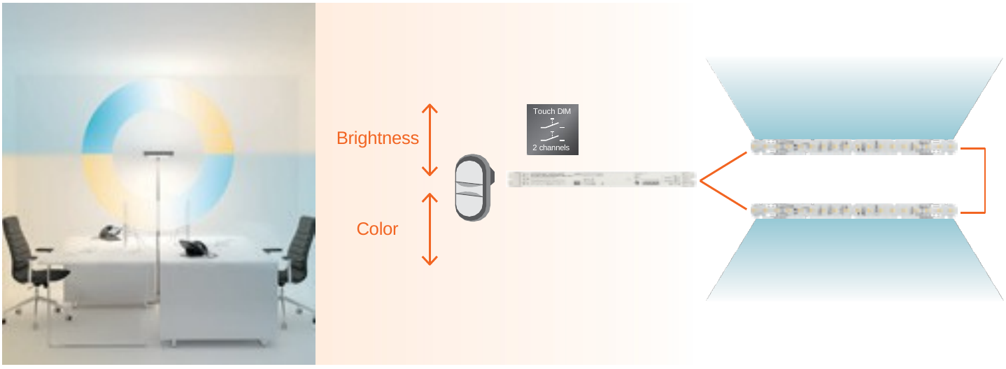
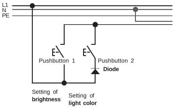
The Inventronics OTi DALI … TW driver is dimmable from 1 to 100 %.
Diode
Use a diode with a rated reverse voltage of at least 700 V, for example 1N4007.
To be connected in any polarity in series to the pushbutton. Clearance and creepage distances must be taken into account when installing the diode.
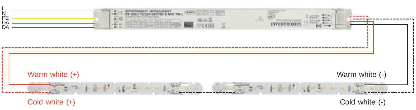
General wiring of the TW driver with Inventronics TW modules
Typical applications of floor-standing luminaires
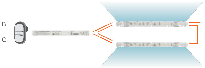
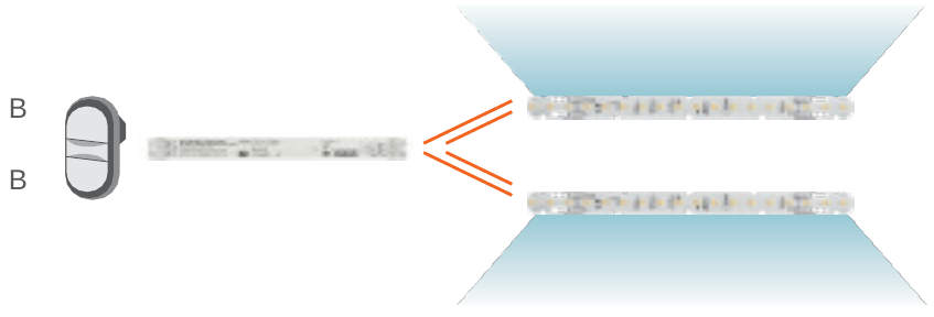
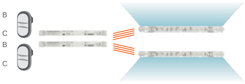
In the following diagrams, B means brightness and C means color.
Synchronized brightness and color
Direct and indirect light share the same brightness and color settings.
- 2 two-color LED modules
- 1 double pushbutton with 1 diode
- 1 TW driver
Independent brightness with single-color modules
Direct and indirect light have separate brightness controls. Color cannot be adjusted.
- 2 single-color LED modules
- 1 double pushbutton with 1 diode
- 1 TW driver
Independent brightness and color
The brightness and color of direct and indirect light can be adjusted independently.
- 2 two-color LED modules
- 2 double pushbuttons with 2 diodes
- 2 TW drivers
Secondary-side wiring of the TW modules
Two-color modules with one driver
- 2 two-color LED modules — PrevaLED® Linear Tunable White
- 1 double pushbutton with 1 diode
- 1 TW driver

Single-color modules with one driver
- 2 single-color LED modules — PrevaLED® Linear
- 1 double pushbutton with 1 diode
- 1 TW driver

Two-color modules with separate drivers
- 2 two-color LED modules — PrevaLED® Linear Tunable White
- 2 double pushbuttons with 2 diodes
- 2 TW drivers
Each module has its own driver:


3 System components
3.1 TW modules
3.1.1 TW module data
To allow the alignment of an LED driver with a TW module in Advanced or Premium Mode, data of the TW module regarding its construction and certain properties must be obtained.
Such data can normally be derived from data sheets of TW modules that usually provide nominal values for luminous flux, color coordinates and forward voltage depending on their nominal operating current.
To improve the performance of a TW system, TW modules may be measured to verify how far the nominal data are met. In case of significant differences between nominal and measured data, the measured data can be implemented in the T4T.
3.1.2 LED data
For an optimal balancing of TW driver and TW module, it is necessary to check the temperature and current dependency of the color coordinates and the efficacy of the LEDs used for a TW module and to enter this information in the T4T (chapter 2.4). When using the Premium Mode, the background calculations carried out in the T4T and in the driver require the following information:
-
The dependency of the color coordinates (cx/cy) on the temperature of the LED
-
The dependency of the color coordinates (cx/cy) on the forward current through the LED
-
The dependency of the luminous flux (lm) on the LED temperature
-
The dependency of the luminous flux (lm) on the forward current through the LED
These data can be found in standard product documentations of the components, e.g. data sheets. They must be entered as described in chapter 3.3 “Configuration tool Tuner4TRONIC® (T4T)”.
These data are not required in the Advanced Mode, where the usual decrease of the luminous flux with increasing component temperature is taken into account with a fixed factor.
3.1.3 Inventronics PrevaLED® TW modules
In case an Inventronics TW module is selected for a project, all relevant data of the module and of the applied LEDs are already available in the T4T.
3.2 Technical features of Inventronics TW drivers
-
DALI DT8: TW or DALI 2 x DT6: 2 channels
-
Analog or hybrid dimming
-
Programmable by DALI/NFC
-
DALI dimming range 1...100 %
-
Very low ripple current ≤ 1 %
-
50,000 h lifetime at tc max = 75 °C
-
Very high efficiency of up to 90 %
-
Low stand-by power consumption < 0.2 W
-
Suitable for emergency lighting
3.2.1 Amplitude/hybrid dimming
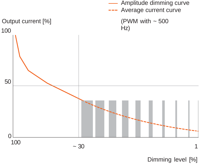
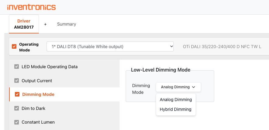
The Inventronics OTi DALI TW drivers offer the possibility to choose the dimming mode between amplitude dimming (default) and hybrid dimming. The picture below shows the difference between these two dimming modes.
Hybrid dimming
Amplitude dimming
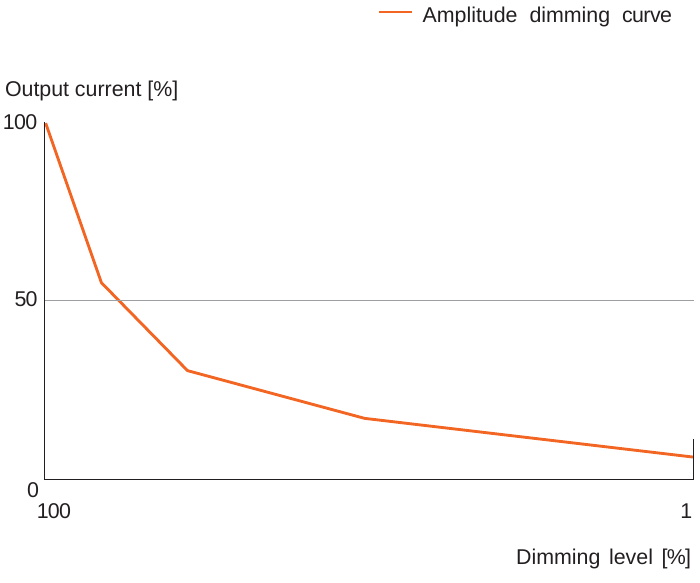
At low dimming levels, amplitude dimming shows a significantly lower light modulation, while at the same time a higher efficiency is achieved.
In the low dimming range, amplitude dimming can lead to (small) color deviations and brightness differences on the LED module. This can be avoided with hybrid dimming, in which the driver changes from amplitude dimming to PWM dimming when the output current falls below 20 mA.
The picture below shows how the dimming mode can be set in the T4T software:
3.2.2 Emergency lighting settings of TW drivers (ex factory)
Ex factory, like all our indoor drivers, the TW drivers provide an active DC detection and adjust the light level/luminous flux to 15 % (DALI value 185). The color temperature is always set to 4000 K, regardless if Inventronics TW modules or TW modules from other manufacturers are used. If higher luminous fluxes are required for emergency lighting, this can be programmed using the T4T configuration tool. Generally, the DC detection can be deactivated if required.
3.3 Configuration tool Tuner4TRONIC® (T4T)
To achieve a good performance of a TW system with an intended color precision, it is necessary to balance drivers with the operated LED modules. Therefore, the T4T also supports data management for TW modules.
This balancing ensures that the calculation of the output currents of the driver considers the specific behavior of the operated LED module in a projected application.
All necessary data, such as LED module data and driver settings, can be implemented and stored in the T4T software.
Data of Inventronics PrevaLED® TW modules are automatically provided by the T4T and can simply be called up.
Since device descriptions of all TW drivers are also stored in the T4T, all possibilities to configure these drivers are provided.
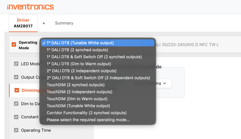
To configure a TW driver, open www.tuner4tronic.com in your browser, click on T4T Configuator – Start, select a TW driver and choose "1x DALI DT8" from the Operating Mode drop-down menu:
In the “Load LED Module” input field, a TW LED module file can be selected from the TW LED module store in the cloud. For entering customized TW LED module files, please refer to chapter 3.3.1. Inventronics TW LED module files can be selected in various combinations (modularity).
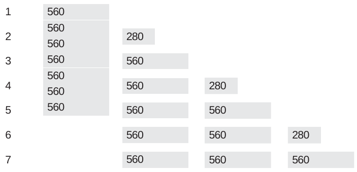
The combinations of PL-LIN-Z1 modules shown above represent any possible total module length that drivers with a maximum output voltage of 240 V can operate. For applications that require other combinations, e.g. 6 modules with 1100 lm, the selection must be made so that the total length of the selected module combination corresponds to the total length of the modules in the application.
3.3.1 Administration of module data: Loading and creation of module data
You can either select a TW LED module file from the TW LED module store or create a new TW LED module file with the TW LED module file generator, upload it to the TW LED module store and then select it in the driver data.
3.3.1.1 Loading of stored TW modules
To load TW LED module files from the LED module store, select the file from the drop-down menu in the "Load LED Module" field.
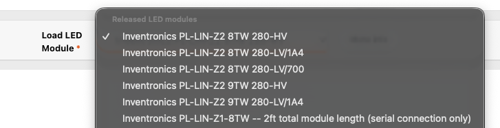
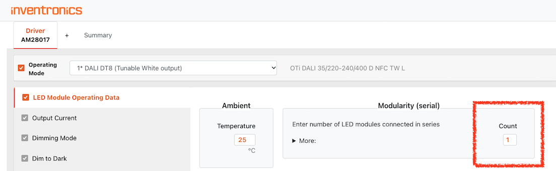
Inventronics TW LED modules are listed in the section "Released Inventronics LED modules". Most LED modules are represented as 1ft modules. To cascade more modules of the same type in series connection, please enter the number of modules in the feature tab "LED Module Operating Data - Modularity"
Please note
The modularity option is not available for customized (non-Inventronics) TW modules.
3.3.1.2 Create or edit new TW modules
In case a new data set is to be created for an LED module, open www.tuner4tronic.com in your browser, click on "Tunable White LED Modules – Start" and "Create/Edit/ Import LED Module". Select the Creation Mode (Basic, Advanced, Premium) to choose the data format.
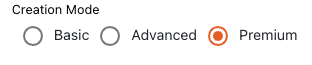
Depending on the selected data model, dedicated feature tabs are displayed in which the TW module data can be edited. The TW module data set can be saved and called up when configuring the driver.
3.3.1.2.1 Input data for data model “Basic Mode”
In the Basic Mode, the CCT values of the two LED types assembled on a TW module must be implemented.
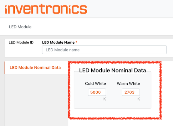
3.3.1.2.2 Data entry for the “Advanced Mode”
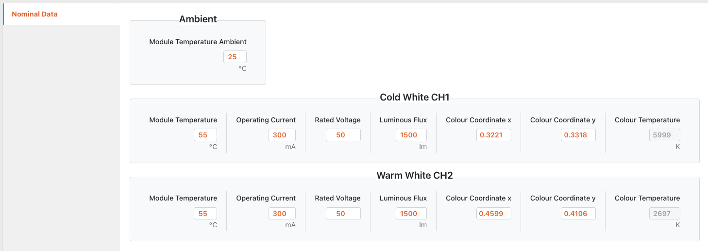
In the Advanced Mode, enter the data for a specific operating point of the module as shown below.
-
Module temperature: The values to be implemented should reflect the temperature that the module reaches when only one channel is operated at nominal (100 %) light output. This allows the different efficacies of both channels to be considered by the current calculation of the driver. While producing equal light levels, the module temperature is usually slightly higher when light is produced by warm white LEDs (compared to cold white LEDs).
-
The combination of all data shall describe one unique operating point of the TW module for each channel. It is advantageous to implement comparable values for the operating current of both channels.
-
The correlated color temperature (CCT) is calculated automatically by the T4T, based on the implemented color coordinates.
-
Enter the ambient temperature of the module that correlates with the data above.
3.3.1.2.3 Input data for data model “Premium Mode”
In the Premium Mode, the nominal data is entered as in Advanced Mode (see chapter 3.3.1.2.2).
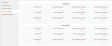
Current dependency
Temperature dependency
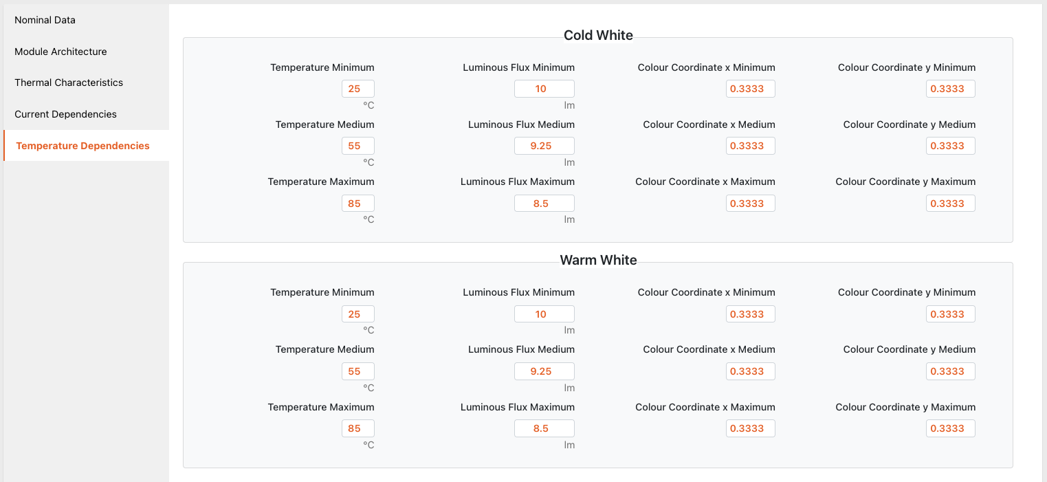
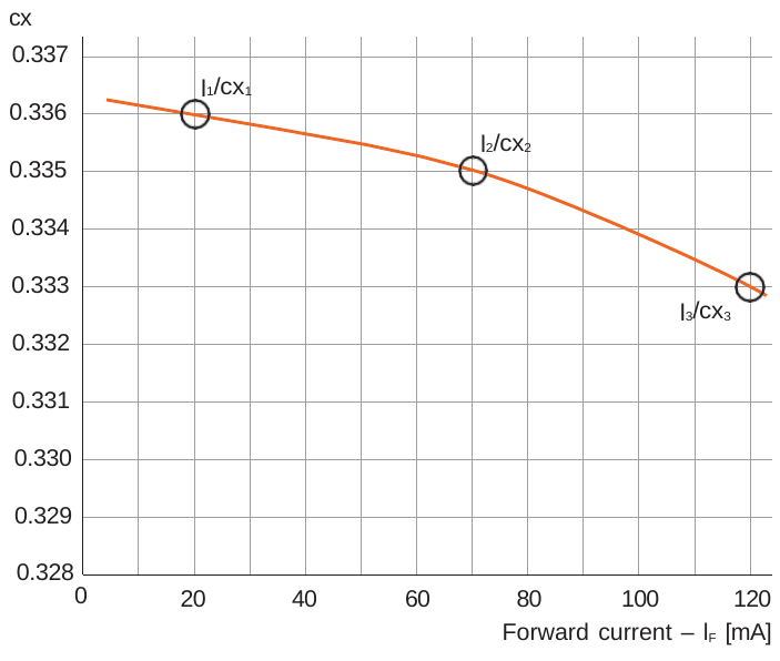
In addition, value pairs for deviating operating points must be derived from the respective LED data sheets. Therefore, the data points must be taken from the characteristic curves of the LEDs.
Example: Three value pairs for the color coordinate cx are derived from the LED data sheet and implemented in the T4T (cx1/l1, cx2/I2, cx3/I3).
3.3.2 Configuration of TW drivers
3.3.2.1 Adjustment of 100 % operating current and balancing with TW module
To configure the driver, an LED module must be selected in the driver settings. Based on the selected TW module, the T4T displays the data derived from the LED module data.
The ambient temperature and module temperatures for each channel can be matched to the specific temperatures in the luminaire. Any change in the editable temperatures will trigger a recalculation of the luminous flux and color coordinates and will affect the color accuracy at low dimming levels.
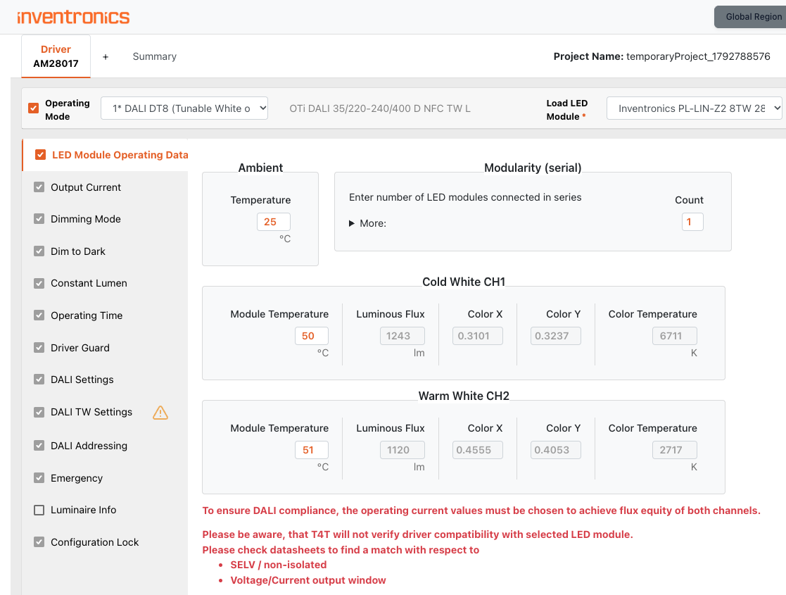
A change of the output current in one channel is reflected in a changed flux. To balance the flux in both channels (i.e. constant total flux with all color settings), please adjust the output current iteratively. A balanced flux is required to comply with the DALI standard.
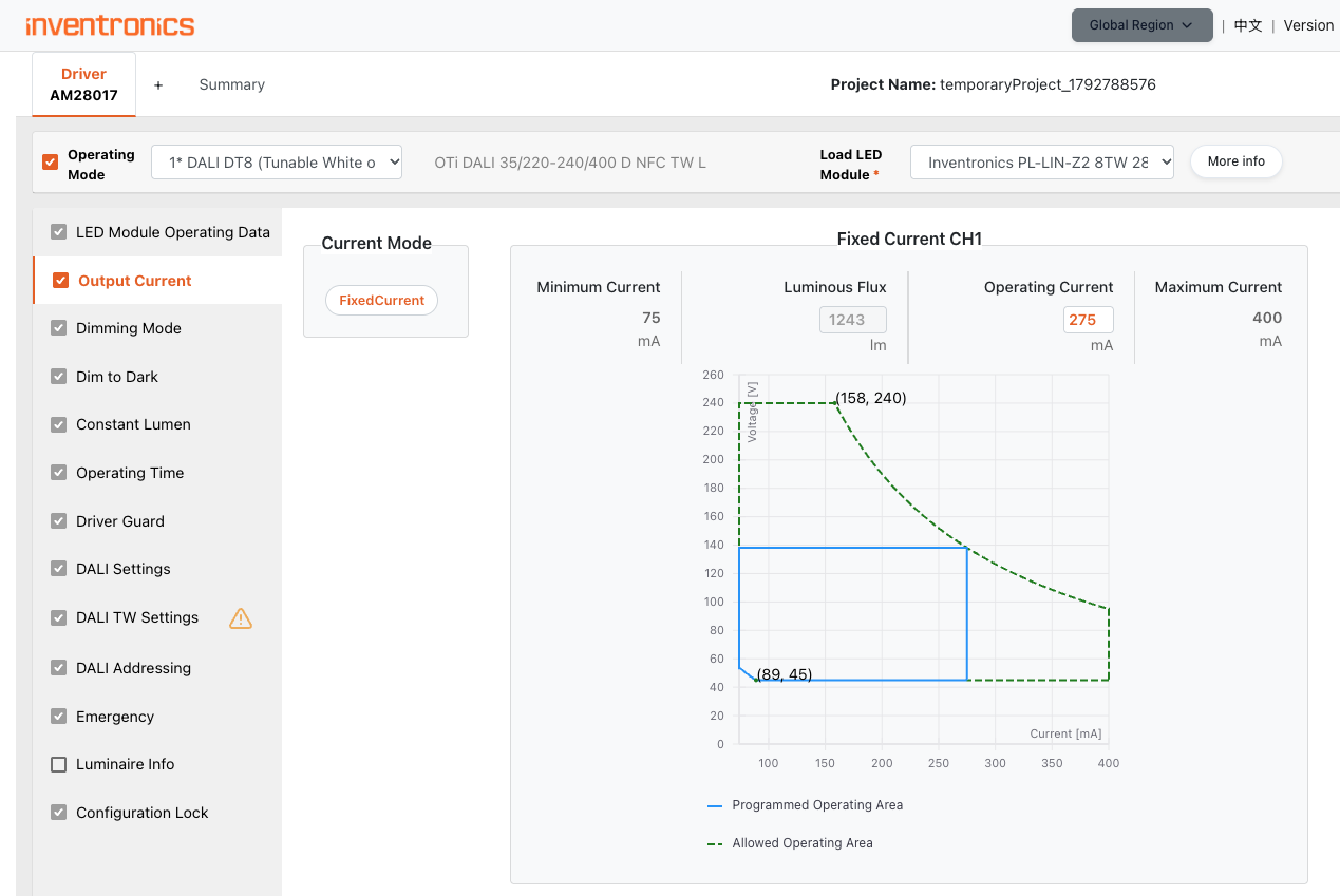
If compliance with the DALI standard is not intended, different current values can also be implemented. This can be done when, for example, an application requires a higher luminous flux with cold white light than with warm white light.
The current values to be entered represent the respective non-dimmed operation of the two channels.
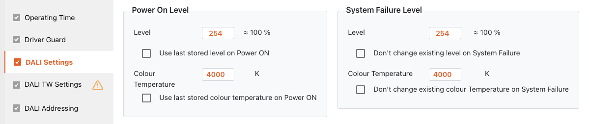
3.3.2.2 Additional DALI settings for LED drivers supporting Tunable White
LED drivers that support Tunable White provide the ability to maintain or set the color temperature and the dimming level when the driver is turned on and after a system failure has occurred.
3.3.2.3 DALI TW settings
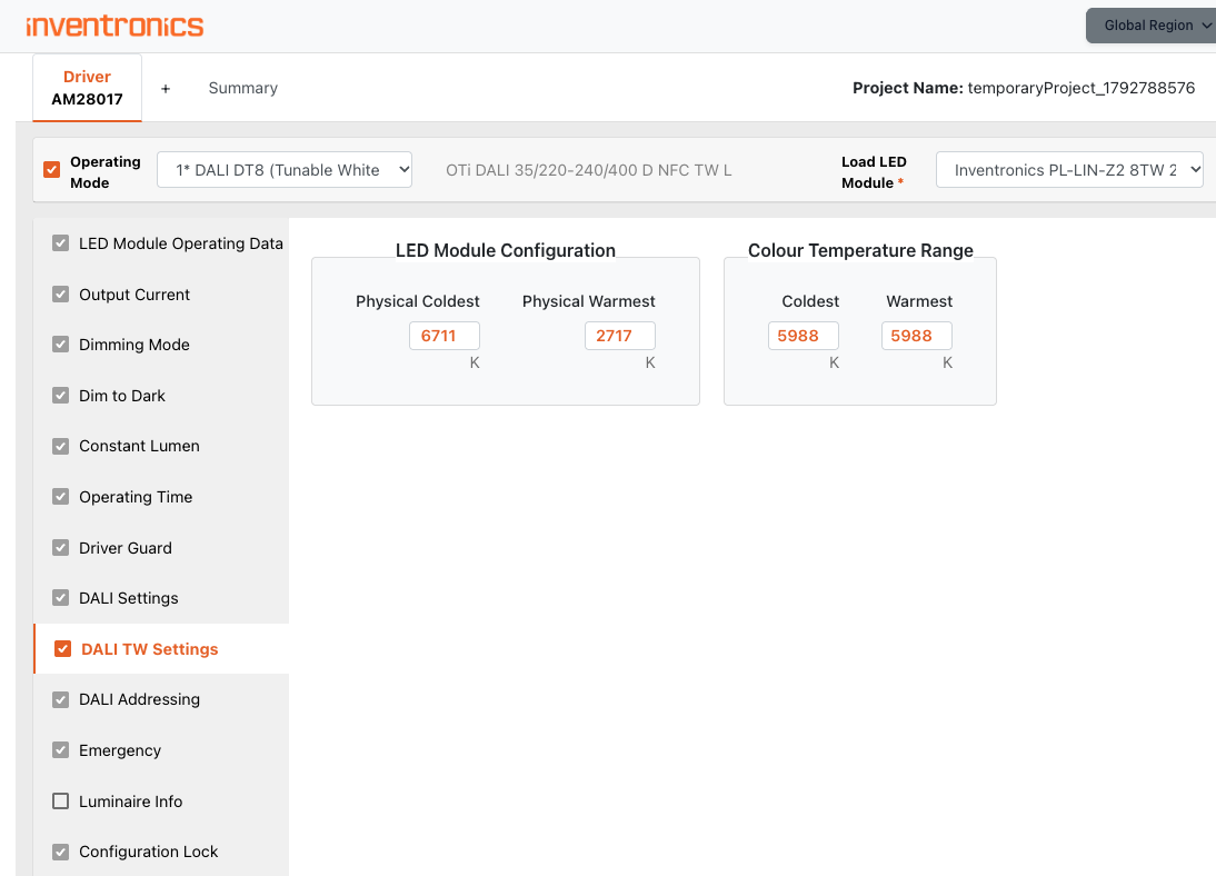
LED drivers that support Tunable White use the following entries in the DALI MemBank:
-
LED Module Configuration (physical limits): These values represent the rated color temperatures of the two LED chains. Default: Values copied from selected LED module data. Values may be trimmed by user, e.g. to eliminate noise effects when dimming at low or high color temperature.
-
Color Temperature Range: These parameters limit the TW operation range within physical limits. Parameters can be modified by DALI controls in the application. Default: Values copied from selected LED module data.
3.3.2.4 Driver operation in single-color operation modes
The driver can also be set for the 2-channel or 1-channel mode for standard applications that only provide light in one color. The appropriate selection must be done in the “Operating Modes” tab of the T4T.
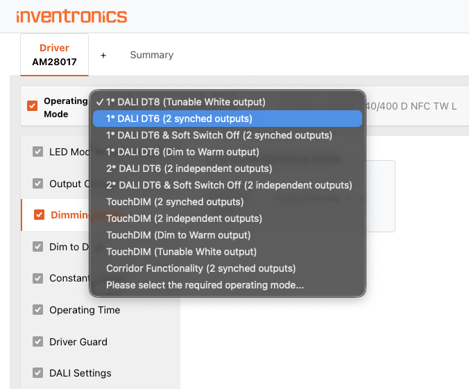
Different types of DALI drivers are defined in the DALI standard as Device Types DTx. Relevant types for LED applications are:
-
DALI DT6: For “standard” LED drivers (one DALI address is used for each DALI driver/ each channel, DALI only provides dimming and switching commands).
-
DALI DT8: For color control (2-channel control gear, one DALI address per driver, DALI provides commands for dimming, switching and color temperature).
Typical applications for 2 x DT6 are: direct/indirect luminaires (2 channels, independently controllable). In this operating mode, the LED driver behaves like two individual LED drivers. Both output channels can be operated almost independently. In function tabs (e.g. operating current), the settings for each channel can be defined individually.
3.4 Light management systems (LMS)
Our lighting concepts can be easily installed and conveniently configured. To cover the entire spectrum of applications, we have various light management systems for every project size and requirement. This opens the door to a cost-effective entry into Tunable White/HCL applications and offers the possibility of selecting more complex and comprehensive solutions adapted to the application and functionalities.
Especially with DALI TW drivers operating in DT8 mode (one DALI address for 2 channels), DALI addresses (compared to 2 DT6 per light point), programming time and costs can be saved in larger lighting installations.
3.4.1 DALI MCU Tunable White
The DALI MCU TW is a simple manual control device for DALI DT8 drivers in the shape of a classic rotary dimmer. It can control the brightness and also the color temperature of light.
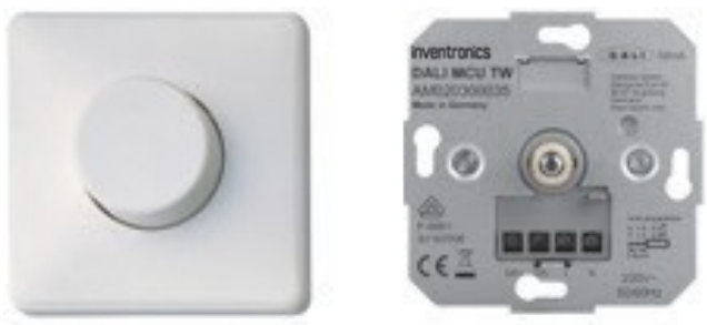
Product benefits
-
Intuitive manual dimming, switching of light and changing of its color temperature
-
Individual setting of minimum brightness level
-
Individual setting of color temperature range
Areas of application
-
Conference rooms
-
Restaurants
-
Shop lighting
-
Residential
Equipment/accessories
-
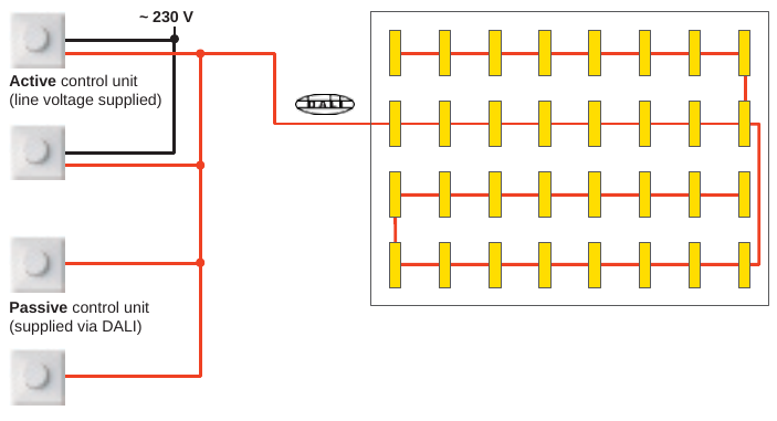
Suitable for up to 25 electronic control gears per active DALI MCU TW, up to 100 ECGs in total with four active DALI MCU TW
-
Cover and rotary knob included (device is also compatible with covers from Jung, Berker, Gira, Siemens and SCHNEIDER Electric)
Product features
-
Up to 4 DALI MCUs can be connected in parallel to set up multiple control points
-
Automatic synchronization between the control points
-
Cover and rotary switch in neutral white
-
Length of the DALI control cable: up to 300 m
Functionality/operation
The brightness is adjusted by turning the knob. The color temperature is set by turning and simultaneously pressing the rotary knob.
Wiring example
3.4.2 DALI ACU BT, DALIeco BT Control and DALI ECO BT RTC Control
The DALI ACU BT and the DALI ECO BT Control are DALI control devices for DALI DT8 drivers, which allow users to control brightness and CCT and to store and recall light scenes with a smartphone via Bluetooth. The DALI ECO BT control can work together with sensors for motion, presence and light detection. DALI ECO BT RTC enables HCL applications for time-controlled brightness and color temperature adjustment thanks to the integrated clock. Time-controlled switching (on/off) and dimming of the lighting is also possible without HCL application.
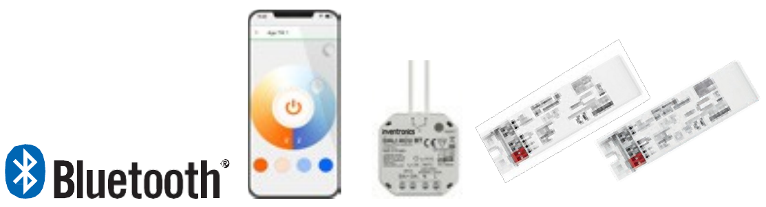
The following tables compare the products as documented in the October 2023 source edition. ✓ indicates a marked entry; — indicates an unmarked entry in the source.
| DALI ACU BT | DALI ECO BT | DALI ECO BT RTC |
|---|---|---|
 |
 |
 |
Product features
| Feature | DALI ACU BT | DALI ECO BT | DALI ECO BT RTC |
|---|---|---|---|
| Compact lighting control device with DALI interface | ✓ | ✓ | ✓ |
| Bluetooth interface for configuration and control via app | ✓ | ✓ | ✓ |
| Integrated clock for time-controlled brightness and color temperature (HCL) | — | — | ✓ |
| Adjustable HCL characteristic with up to 24 points | — | — | ✓ |
| One DALI output channel (broadcast or groupcast) | ✓ | ✓ | ✓ |
| Up to 32 DALI luminaires can be connected | ✓ | ✓ | ✓ |
| Can be combined with Inventronics DALI sensors and DALI pushbutton couplers | ✓ | ✓ | — |
| Supports up to four Inventronics DALI sensors and DALI pushbutton couplers | — | — | ✓ |
| Daylight-dependent adjustment and presence-dependent lighting control | ✓ | ✓ | ✓ |
| Separate pushbutton input for operation via standard pushbutton | ✓ | ✓ | — |
| Pushbutton interface for separate operation of brightness and color temperature | — | — | ✓ |
| Supports DALI DT8 Tunable White drivers | ✓ | ✓ | ✓ |
| Outputs with electronically reversible overtemperature, short-circuit and overload protection | ✓ | ✓ | ✓ |
| Cable length of the DALI control line up to 300 m | ✓ | ✓ | ✓ |
| Cable length to the pushbutton up to 50 m | ✓ | ✓ | ✓ |
| Suitable for switch box integration | ✓ | — | — |
| Suitable for luminaire integration | — | ✓ | ✓ |
Product benefits
| Feature | DALI ACU BT | DALI ECO BT | DALI ECO BT RTC |
|---|---|---|---|
| Daytime-dependent adjustment of brightness and color temperature (HCL) | — | — | ✓ |
| Suitable for Human Centric Lighting (HCL) applications | — | — | ✓ |
| Lighting control via smartphone | ✓ | ✓ | ✓ |
| Adjustment of all setting options via smartphone | ✓ | ✓ | ✓ |
| Up to four timers with adjustable on/off time and weekday | — | — | ✓ |
| Plug and play — basic functions available without app | ✓ | ✓ | — |
| Simplified commissioning thanks to predefined function modes | ✓ | ✓ | ✓ |
| Intuitive manual dimming, switching and setting of color temperature | ✓ | ✓ | ✓ |
| Separate control of up to four groups | ✓ | ✓ | ✓ |
| Adjustable offset for different groups | ✓ | ✓ | ✓ |
| Easy scene generation in the app | ✓ | ✓ | ✓ |
| Scene recall possible via Inventronics DALI PRO PB pushbutton coupler | ✓ | ✓ | ✓ |
| Wireless firmware update possible via Bluetooth | ✓ | ✓ | ✓ |
| Integrated DALI supply | ✓ | ✓ | ✓ |
| Control of Standard White or Tunable White light according to DALI Device Type 8 (DT8) | ✓ | ✓ | ✓ |
| Selected DALI parameters adjustable via app | ✓ | ✓ | ✓ |
Areas of application
| Application | DALI ACU BT | DALI ECO BT | DALI ECO BT RTC |
|---|---|---|---|
| Floor-standing lamps | — | ✓ | ✓ |
| Offices | ✓ | ✓ | ✓ |
| Conference rooms | ✓ | ✓ | ✓ |
| Training rooms | ✓ | ✓ | ✓ |
| Classrooms | ✓ | ✓ | ✓ |
| Corridors | ✓ | ✓ | ✓ |
| Shop lighting | ✓ | ✓ | ✓ |
Equipment and accessories
| Feature | DALI ACU BT | DALI ECO BT | DALI ECO BT RTC |
|---|---|---|---|
| Free app for iOS and Android available in the App Store | ✓ | ✓ | ✓ |
| Ceiling integration or independent installation possible via ECO CI KIT | — | ✓ | ✓ |
3.4.3 DALI PROFESSIONAL
The DALI PROFESSIONAL light management system provides a wide range of functions, such as controlling light colors (RGB), color temperatures and dynamic color changes. These features round up standard functions such as switching, dimming, presence detection and daylight-dependent lighting control. Moreover, the system can easily be integrated into your KNX system.
The new interface KNX IF 250 ensures the bidirectional data exchange between DALI PROFESSIONAL and a KNX system so that centralized functions, such as switching and dimming as well as individual lighting control can be executed via KNX.
Areas of application
-
Room control, floor control, daylight-dependent control
-
Connection of light and presence sensors in DALI systems
-
Conference rooms
-
Offices: Individual and group workplaces
-
Production and assembly facilities
-
Suitable for indoor applications
-
Large luminaire groups
-
Industry
-
Corridors
-
Strip lighting
-
Logistics centers
-
Classrooms
-
Sports halls
-
Training rooms
DALI Pro Control app
With the DALI Pro Control app, the functions of the DALI PROFESSIONAL system can be conveniently adapted. Several users can access the control system in parallel.
The app features at a glance
-
Convenient switching and dimming of lighting with status display
-
Clear structure through grouping in rooms
-
Access restriction with individual release of each control element for each user
-
Activating/overriding daylight controls
-
Calling up static lighting scenes and dynamic sequences
-
Control element for colored light (RGB)
-
Control element for changing the color temperature (TW)
3.4.4 DALI PRO RTC
The DALI PRO RTC is a fully programmable DALI control system for medium to large DALI installations. It can also control DT8 devices and is controllable with a smartphone via Wi-Fi. The DALI PRO RTC can also perform daylight simulation.
Product features
-
Interconnection of up to four DALI PRO RTC control units
-
Configuration via LAN/WLAN/USB
-
RGB color sequences
-
Time-of-day-dependent color temperature adjustment (Human Centric Lighting)
-
Controller for four DALI lines
-
Up to 50 pushbutton/sensor couplers can be integrated
-
Integrated DALI supply
-
Four freely programmable switchover relays; load contact: 4 x 5 A
-
Daylight-dependent and/or presence-dependent or manual control
-
Up to 4 x 16 groups can be controlled
-
Integrated clock for event control
-
Weekly scheduler
-
Connection via push-in terminals
-
Control of lighting scenes and sequences (recall/store)
-
Housing for series installation
-
Length of the DALI control cable: up to 300 m
Product benefits
-
Easy and intuitive control via app
-
Control of up to 1024 DALI ECGs via LAN interconnectivity
-
Plug and Play preconfigured for instant use without any startup procedure
-
Mains voltage interruption buffer battery
-
All the luminaires in the system can be dimmed or switched
-
Simple creation of scenes and sequences
-
Switching and dimming of up to 256 DALI ECGs per DALI PROFESSIONAL control unit
-
A setpoint for daylight-dependent control can be stored by double clicking
-
Sensor integration in DALI
-
Remote access/remote maintenance
-
Due to the KNX interface, DALI PRO RTC can also be integrated into building management systems
Equipment/Accessories
-
DALI PRO PC software
-
Free end-user mobile app for iOS and Android
For more information, please refer to the data sheet and instruction sheet at www.inventronics-light.com/dalipro.
3.4.5 DALI PRO 2 IoT
DALI PRO 2 IoT is the innovative LMS control technology for the IoT age. DALI-2-certified and featuring a controller for two DALI lines as well as a built-in gateway, it meets all of today's requirements for professional and efficient light management. Thanks to its browser-based graphical user interface, commissioning the system is as fast and easy as never before.
Energy Monitoring and Maintenance Assistant
In combination with our cloud technology, the DALI PRO 2 IoT system enables facility managers and other users to monitor their lighting installations via the EM/MA dashboard. All they need is Internet access and a respective subscription.
Product features
-
DALI-2-certified
-
Controller for two DALI lines
-
Built-in gateway
-
Browser-based graphical user interface
-
Form factor of 6 TE (DIN rail)
-
Backwards compatible with PC tool and mobile app
Product benefits
-
Improved product interoperability
-
Standardization of system components such as sensors and controllers
-
Monitor energy consumption and maintenance data via cloud application
-
Connect up to 128 drivers and 126 input devices (sensors, couplers etc.)
-
A simple commissioning tool without the need of downloading software
-
Connection via on-site local network or controller’s own Wi-Fi network
-
Work with familiar tools and apps
Equipment/Accessories
-
USB Wi-Fi dongle (included)
-
DALI PRO PC software
-
DALI PRO 2 IoT browser-based graphical user interface
-
Free end-user mobile app for iOS and Android
References/Links
- Configuration software available at www.inventronics-light.com/software
4 Handling
4.1 Wiring
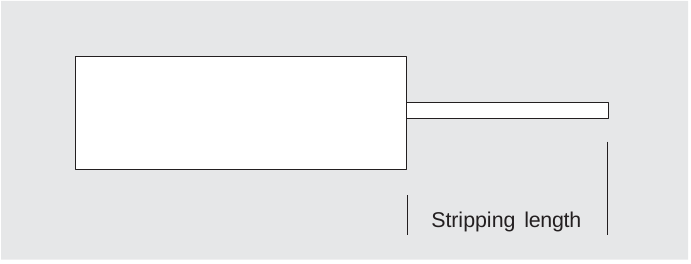
The terminals of the PrevaLED® Linear Tunable White LED module are suitable for rigid and flexible conductors with a cross-section of 0.2 mm² to 0.75 mm² (AWG 24–18). Rigid wires are recommended.

Strip the conductors to a length of 8 to 9 mm and insert them axially into the terminal at an angle of 0°.
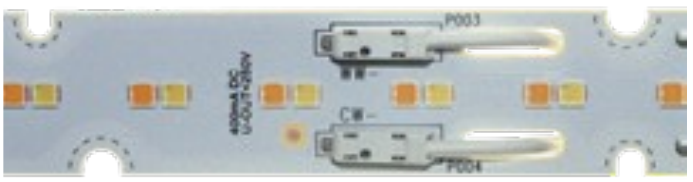
The module bushings allow wiring from the rear to avoid unwanted shadows.
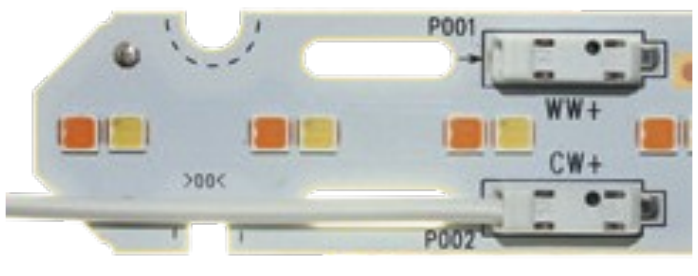
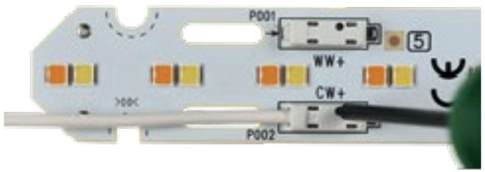
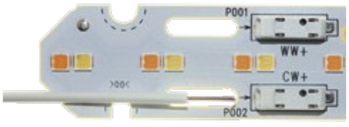
4.2 Release connections
The connectors provide a simple insertion and release mechanism. Solid wires can be inserted directly. For stranded wires, press the release mechanism on top of the connector to simplify insertion. Use the same mechanism to release the wire.
- Locate the connected wire and the connector release mechanism.
- Press the release mechanism on top of the connector.
- Withdraw the wire from the terminal.
4.3 Electrostatic discharge (ESD)
The PrevaLED® modules meet the requirements of IEC/ EN 61547. It must be considered that an electrostatic discharge exceeding 2 kV HBM (Human Body Model) can lead to a damage or even a complete failure of the module.
We therefore recommend that the storage and handling of PrevaLED® Linear TW modules are carried out in accordance with the acknowledged methods for protection against ESD damage.
4.4 NFC programming
Position the NFC programmer as shown in the illustration. NFC programming is only possible while mains voltage is not connected to the LED driver.
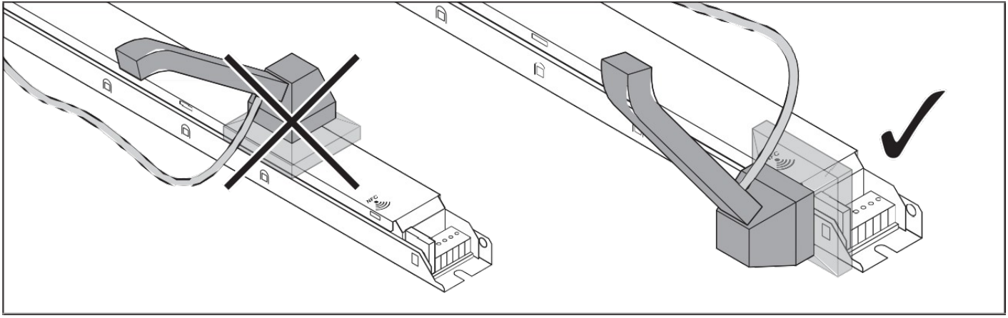
Further information is available in the Tuner4TRONIC manual.
4.5 Exemplary assembly of a five-foot TW luminaire with 5500 lm
Warning: Do not use non-isolated modules together with SELV modules!
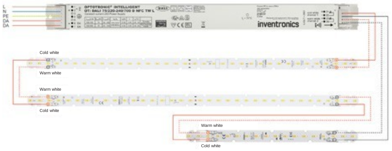
Example for interconnection with non-isolated modules
Electrical parameters of PL-LIN-Z2 2200-8TW 560x20-HV:
Forward current If = 275 mA
Forward voltage Vf = 46.4 V, P = 12.8 W
Non-isolated module 3 (280 mm)
Electrical parameters of a PL-LIN-Z2 1100-8TW 280x20-HV:
Forward current If = 275 mA
Forward voltage Vf = 23.2 V, P = 6.4 W
Series connection of the three modules
Forward current If = 275 mA
Forward voltage Vf = 2x 46.4 V + 23.2 V = 116.0 V, P = 32 W
From our non-isolated LED driver portfolio, the OTi DALI 35/220–240/400 D NFC TW L with its operating range perfectly fits this non-isolated module selection.
Example for interconnection with 700 mA SELV modules
Electrical parameters of PL-LIN-Z2 2200-8TW 560-LV/700: Forward current If = 550 mA
Forward voltage Vf = 20.6 V, P = 11.3 W
SELV module 3 (280 mm) 700 mA LV
Electrical parameters of a PL-LIN-Z2 1100-8TW 280-LV/700: Forward current If = 550 mA
Forward voltage Vf = 10.3 V, P = 6.4 W
Series connection of the three modules
Forward current If = 550 mA
Forward voltage Vf = 2x 20.6 V + 23.2 V = 51.0 V, P = 29 W
Source inconsistency: The preceding 280 mm module is specified at 10.3 V. The printed expression uses 23.2 V, while the stated total of 51.0 V corresponds to 2 × 20.6 V + 10.3 V. Confirm the module data before applying this example.
From our SELV LED driver portfolio, the OTi DALI 35/220-240/700 NFC TW L with its operating range perfectly fits this SELV module selection.
Example for interconnection with 1A4 SELV modules
Also available in CRI 90 which cannot be mixed with CRI 80 modules.
SELV modules 1 and 2 (560 mm) 1,400 mA LV
Electrical parameters of PL-LIN-Z2 2200-8TW 560-LV/1A4: Forward current If = 1,100 mA
Forward voltage Vf = 10.3 V, P = 11.3 Watt
SELV module 3 (280 mm) 1,400 mA LV
Electrical parameters of a PL-LIN-Z2 1100-8TW 280-LV/1A4: Forward current If = 1,100 mA
Forward voltage Vf = 5.1 V, P = 5.6 W
Series connection of the three modules
Forward current If = 1,100 mA
Forward voltage Vf = 2x 10.3 V + 5.1 V = 25.7 V, P = 28.2 W
From our SELV LED driver portfolio, the OTI DALI 75/220-240/1A4 NFC TW L with its operating range perfectly fits this SELV module selection.
5 Thermal considerations
No additional heat sink is necessary to avoid that tc max is exceeded when a PrevaLED® Linear TW is operated at nominal operating conditions and mounted onto or into a luminaire housing with heat exchange to the ambience.
To avoid overheating, it is nevertheless strongly recommended to check the LED module temperature in any newly designed luminaires.
It should also be mentioned that lower tc point temperatures of the LED module increase the module’s efficiency. Therefore, efficient cooling for the LED modules increases the system efficiency of the luminaire/application.
5.1 Introduction and definitions
For any LED module, different temperatures (tp, tc, tc max etc.) are mentioned in the data sheet. They are sometimes mixed up, therefore a short overview is given:
- tp is the performance temperature of the module.
This means that all the tables, diagrams and numbers in the data sheet (and in this technical application guide) refer to the performance temperature tp (if not mentioned otherwise).
- tc max is the absolute maximum temperature up to which the operation of the LED module is allowed.
All temperature values mentioned above are measured at the position on the LED module, which is called the “tc point” of the LED module. Its position on the modules is shown on the next page.
5.2 tc point position and measurement
Proper thermal design is essential for achieving best performance and a long lifetime. Verify that the light engine dissipates sufficient heat by measuring the temperature at the tc point.
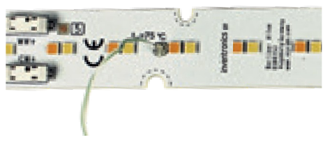
The maximum temperature at the tc point must not exceed 75 °C. The illustration shows the measurement point on PrevaLED® Linear TW modules; its position is similar on other comparable module types.

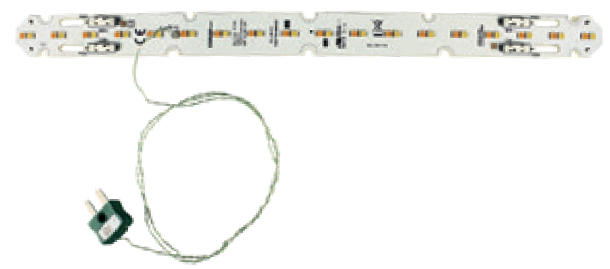
The easiest measurement method is a thermocouple glued to the LED module. Fix it in direct contact with the tc point and ensure it does not touch conductive parts.
Examples of suitable thermocouples
A K-type thermocouple with NiCr–Ni thermowire and a miniature K connector can be used.

| Thermocouple | Temperature range | Illustration |
|---|---|---|
| PVC-insulated | −10 to +105 °C | 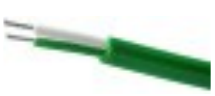 |
| PFA-insulated | −75 to +260 °C | 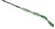 |
| Sprung | −75 to +260 °C | 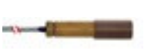 |
Module with a glued-on thermocouple
The following photographs show a PrevaLED® Linear TW module with a glued-on thermocouple and a close-up of its attachment.
Thermal considerations for LED drivers
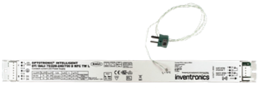
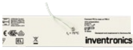
Locate the tc measurement point on the OTi DALI TW driver as shown below.

The following photographs show the driver with a mounted thermocouple and a close-up of its attachment.
6 Mechanical considerations
6.1 Mechanical protection
For operation in damp, wet or dusty environments, adequate ingress protection (IP) must be ensured with a suitable luminaire.
6.2 Mounting instructions
Apply force only to the dedicated mounting positions. Strong mechanical stress can irreversibly damage the LED module. Use M4 screws according to DIN 7984 to fix the module into the luminaire housing.
Without an isolating washer between the screw and the mounting hole, the maximum permissible screw head diameter is 7.5 mm. Larger screw heads can reduce the required creepage distances between the screw and other conductive parts.
| Screw shown in the source | Diameter | Head diameter | Head height |
|---|---|---|---|
| Cylinder head, Torx drive M4 (ISO 4762) | 4.0 mm | 7.0 mm | 4.0 mm |
| Torx, hexagon socket, button head M4 (ISO 7380) | 4.0 mm | 7.5 mm | 2.1 mm |
The maximum torque depends on the screw type, luminaire material, and use of washers. In most cases, 0.5 Nm to 1 Nm is sufficient to fix the module without damaging it.
For optimal fixation and thermal management, use all mounting holes of the same diameter, either all 3 mm or all 4 mm holes. If fewer screws are used, verify thermal behavior and mechanical strength.
Perform mechanical and thermal testing of the LED modules in the luminaire.
Disclaimer
All information contained in this document has been collected, analyzed and verified with great care by Inventronics.
However, Inventronics is not responsible for the correctness and completeness of the information contained in this document and Inventronics cannot be made liable for any damage that occurs in connection with the use of and/or reliance on the content of this document. The information contained in this document reflects the current state of knowledge on the date of issue.
Service contact
Inventronics GmbH
Parkring 31–33, 85748 Garching, Germany
www.inventronics-light.com
support@inventronicsglobal.com