
Tuner4TRONIC Simple Current Programming (T4T-S) - User Manual
Set driver output current via NFC with T4T-S, protect settings with Configuration Lock, program batches, and maintain the driver database.
Updated · by Administrator
On this page
- Please note
- 1 About Tuner4TRONIC Simple Current Programming
- 2 Using T4T Simple Current Programming
- Service contact
Tuner4TRONIC Simple Current Programming (T4T-S) - User Manual

This manual covers T4T - Simple Current NFC Programming 4 and is based on the updated May 2024 manual.
Please note
All information in this guide has been prepared with great care. Inventronics, however, does not accept liability for possible errors, changes and/or omissions. Please check www.inventronicsglobal.com or contact your sales partner for an updated copy of this guide.
This technical application guide is for information purposes only and aims to support you in tackling the challenges and taking full advantage of all opportunities the technology has to offer. It is based on Inventronics' own measurements, tests, specific parameters and assumptions. Individual applications may not be covered and may need different handling. Responsibility and testing obligations remain with the luminaire manufacturer/OEM/application planner.
1 About Tuner4TRONIC Simple Current Programming
1.1 Purpose and application
The Tuner4TRONIC Simple Current Programming Tool (T4T-S) allows output current setting in Inventronics wide-range LED drivers via NFC instead of LEDset, while retaining default settings for the other driver functions. T4T-S can operate without a permanent internet connection. Without internet access, update the driver database manually.
T4T-S does not require Production Files: it reads data from a sample driver and sets the output current in drivers of the same type.
Important: The tool checks minimum and maximum current limits, but applies no other validation rules. Ensure that the output current does not interfere with other driver settings, such as DALI settings, constant lumen output (CLO) or the tuning factor. Use T4T-S with blank drivers with default settings whenever possible.
Warning: Password protection is recommended to prevent unauthorized reprogramming. Exceeding the light engine's rated current may cause defects in the luminaire.
To use the full functionality of LED drivers, use the T4T tool chain with T4T Configurator, T4T Production and the T4T Field app. Tuner4TRONIC tools are available from the Inventronics Tuner4TRONIC page.
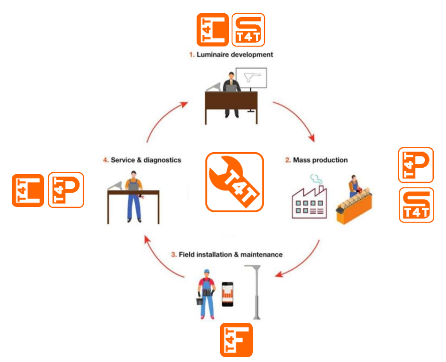
The Tuner4TRONIC software suite allows luminaire manufacturers to program Inventronics drivers via DALI and/or NFC in a simple, fast, reliable and cost-effective way, speeding up production. Interface support depends on the module used.
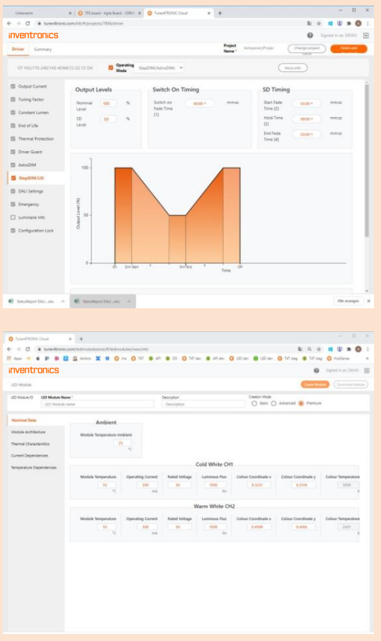
Tuner4TRONIC Configurator
This browser application lets luminaire designers configure LED drivers by setting output current, dimming levels, constant lumen output, operating modes and other parameters. Its multi-level password system, Configuration Lock, protects drivers against unauthorized changes while allowing service technicians access to selected features.
After configuration, settings are exported as an encrypted, read-only Production File and sent to the production line. Open the Configurator at www.tuner4tronic.com.
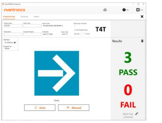
Tuner4TRONIC Production
Factory workers load encrypted Production Files to start automatic programming for fast mass production of LED drivers. The application provides a multilingual user interface.
Tuner4TRONIC Machine
DLL and command line tools integrate Inventronics LED driver programming into automatic programming stations on the production line.
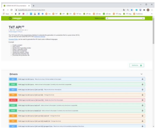
Tuner4TRONIC REST API
While Configurator, Development and Production provide graphical interfaces, the API provides functions and tools for software developers to create luminaire configurations automatically. A typical use is creating luminaire files when a new order arrives in an ERP system.
The API uses REST standards and conventions and comes with comprehensive documentation. A software developer must integrate it into your system; Inventronics does not provide ERP system integrations.
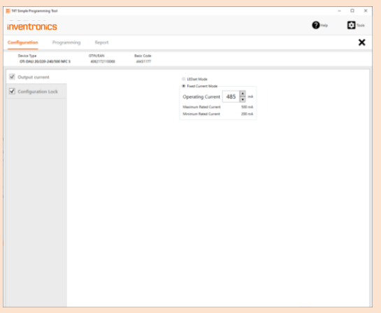
Tuner4TRONIC Simple Current Programming
This PC tool programs driver output current without creating Production Files. Read data from a driver, edit the output current and upload the current setting to drivers of the same type. The tool also supports password protection.
Tuner4TRONIC Field
The smartphone app programs Inventronics outdoor OT 1DIM and OT 4DIM drivers and indoor OTi DALI Compact LED drivers via NFC, wirelessly and without mains voltage. It can change light output and dimming levels, and copy a driver configuration to another driver.
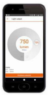
See the Tuner4TRONIC Field App user manual for instructions.
1.2 File types
The source manual lists these file types for Tuner4TRONIC Development and the wider tool chain:
| File type | Extension |
|---|---|
| Tuner4TRONIC Production File | .osrtup |
| Driver description file | .osrtud |
| Driver data in raw format | .osrtur |
| Password file | .osrpwd |
| Tuner4TRONIC luminaire project file (phased out) | .osrtul |
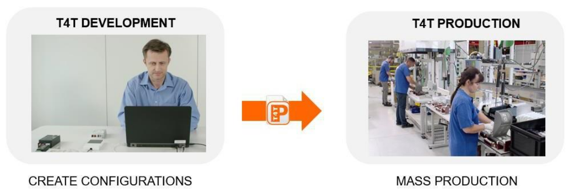
1.3 Workflow between T4T versions
- The luminaire product manager or designer creates the required configuration, such as operating current, CLO and dimming, in T4T Configurator. The optional T4T API can create luminaire and Production Files directly from an ERP system.
- When configuration is complete, export a read-only
.osrtupProduction File and send it to the assembly line. - At the assembly line, load the file in T4T Production and start mass programming. Alternatively, use T4T Machine DLL and command line tools to integrate with automatic programming and testing stations.
1.4 System requirements
Minimum requirements listed in the May 2024 manual:
- 1 GB main memory.
- Windows 8, Windows 8.1 or Windows 10, 32-bit or 64-bit, with the latest service pack installed.
- 200 MB hard disk space.
- A monitor with a resolution of 1024 × 768 pixels; recommended zoom factor: 100%.
- One free USB 2.0 port for the programming interface.
1.5 Programming interfaces
A suitable programming interface is required for the driver being used. The source manual illustrates the following interfaces for the Tuner4TRONIC suite:
| Interface | Notes |
|---|---|
| FEIG ISC.PRH101 | Single programming only |
| FEIG CPR30 | NFC programming interface |
| FEIG ISC.MR102 | Separate ISC.ANT310/310 antenna required |
| FEIG ISC.LR1002 | Separate ISC.ANT310/310 or ISC.ANT800/600 antenna required |
| ID ECCO Smart HF.BLE | FEIG order code 5738.000.00 |
| ID BLE USB-Dongle | FEIG order code 5903.000.00; required for Bluetooth connection with ECCO Smart |
| DALI magic | DALI programming interface |
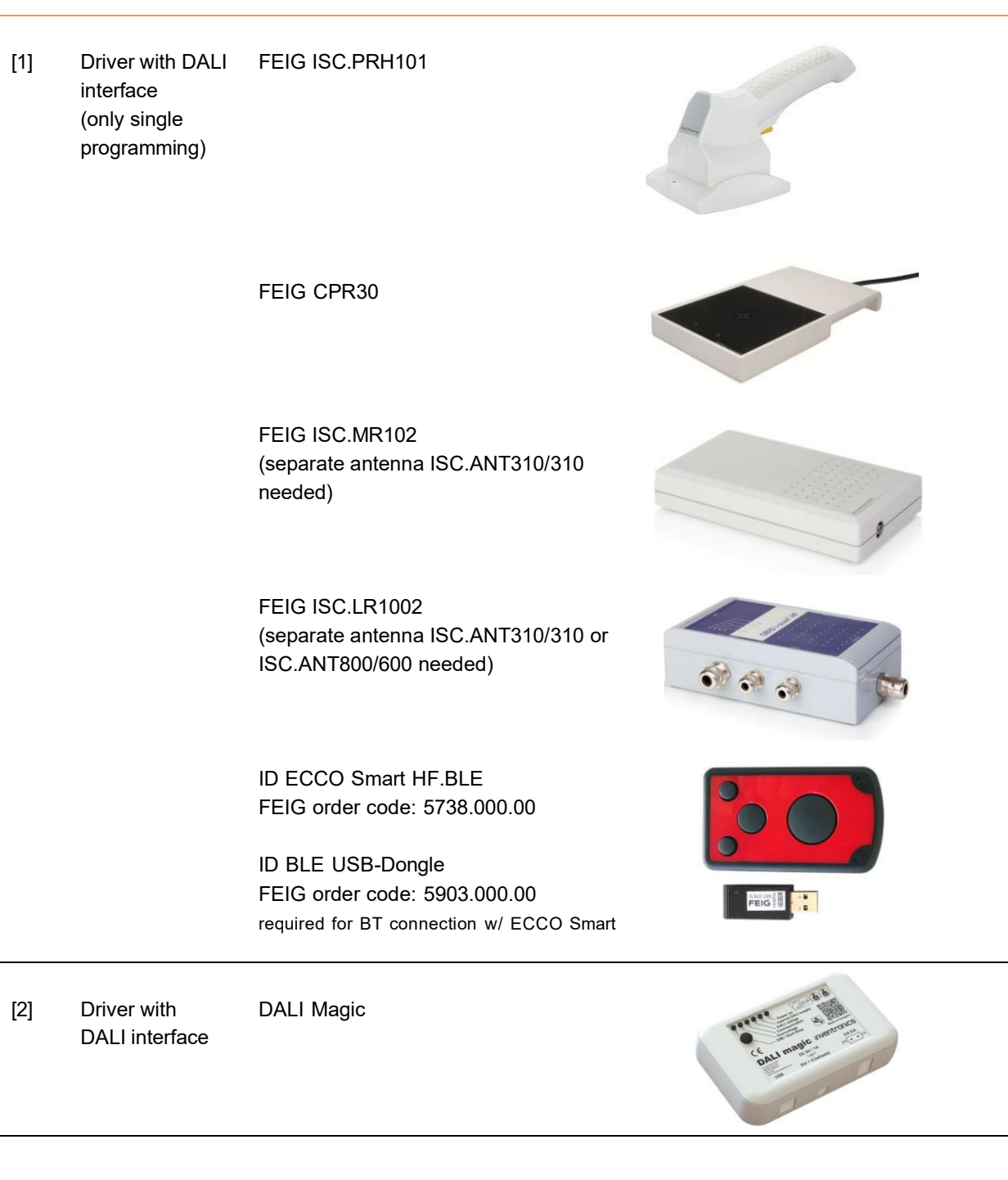
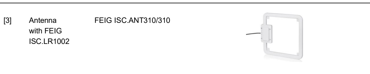
Tuner4TRONIC can handle more than one programming interface connected to the same PC.
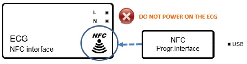
1.6 Prepare a driver with an NFC interface
- Connect the FEIG PRH101, FEIG CPR30 or FEIG MR102 programming interface to the PC with the supplied USB cable.
- Place the interface antenna close to and in contact with the driver's NFC area, identified by the NFC logo.
- Keep the driver and programming interface stationary until the process is complete.
Important: Keep the driver powered OFF during NFC programming unless the driver's documentation states otherwise. Keep the interface antenna and the driver's NFC area close together throughout the complete programming process.
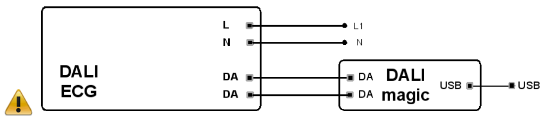
1.7 Prepare a driver with a DALI interface
- Connect DALI magic to the PC using the supplied USB cable.
- Connect the external 6 V DC power supply to DALI magic. This is mandatory when more than four drivers are connected to the DALI line and is strongly recommended in all cases to improve communication stability.
- Connect the driver to mains and to protective earth (PE), if the driver has the corresponding terminal.
- Connect the DALI terminals of DALI magic to the DALI inputs of the driver or drivers.
Most DALI LED drivers allow programming with a low-voltage supply, such as 48 V, instead of mains voltage. Consult the driver's datasheet for details.
1.8 Software installation
Read the Release Notes in the ZIP file before installation. Windows administrator rights are required.
- Extract the Tuner4TRONIC ZIP file to your local hard drive.
- Run
Install T4T.exefrom the extracted folder. Running the installer from inside the ZIP file causes a faulty installation. - Launch Start > Tuner4TRONIC 4 > SimpleCurrent, or double-click the desktop icon.
2 Using T4T Simple Current Programming
2.1 Start page
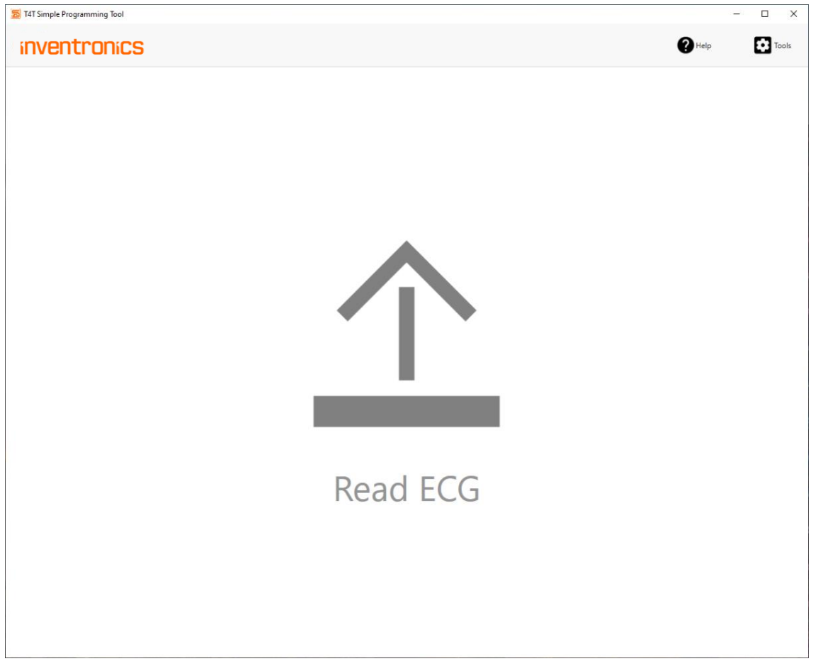
| Control | Function |
|---|---|
| Read ECG | Read data from the connected driver through the NFC or DALI programming interface. After a successful read, the application opens the programming page. |
| Tools | Open the tools page. |
| Help | Open help and about pages. |
2.2 Programming page - configuration
Output current and order code
After a driver is read, the header displays its name, EAN and IC base code. In Output current, enter a value within the driver's minimum and maximum limits. The default value is the output current read from the driver.
Programming deactivates LEDset and switches the current setting mode to Fixed Current Mode.
Enter an optional Order Code to track programming events in the report.
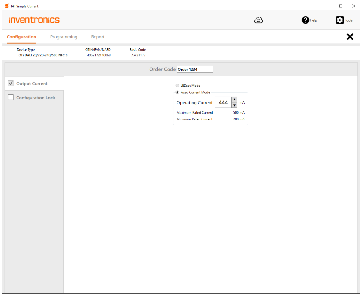
Configuration Lock
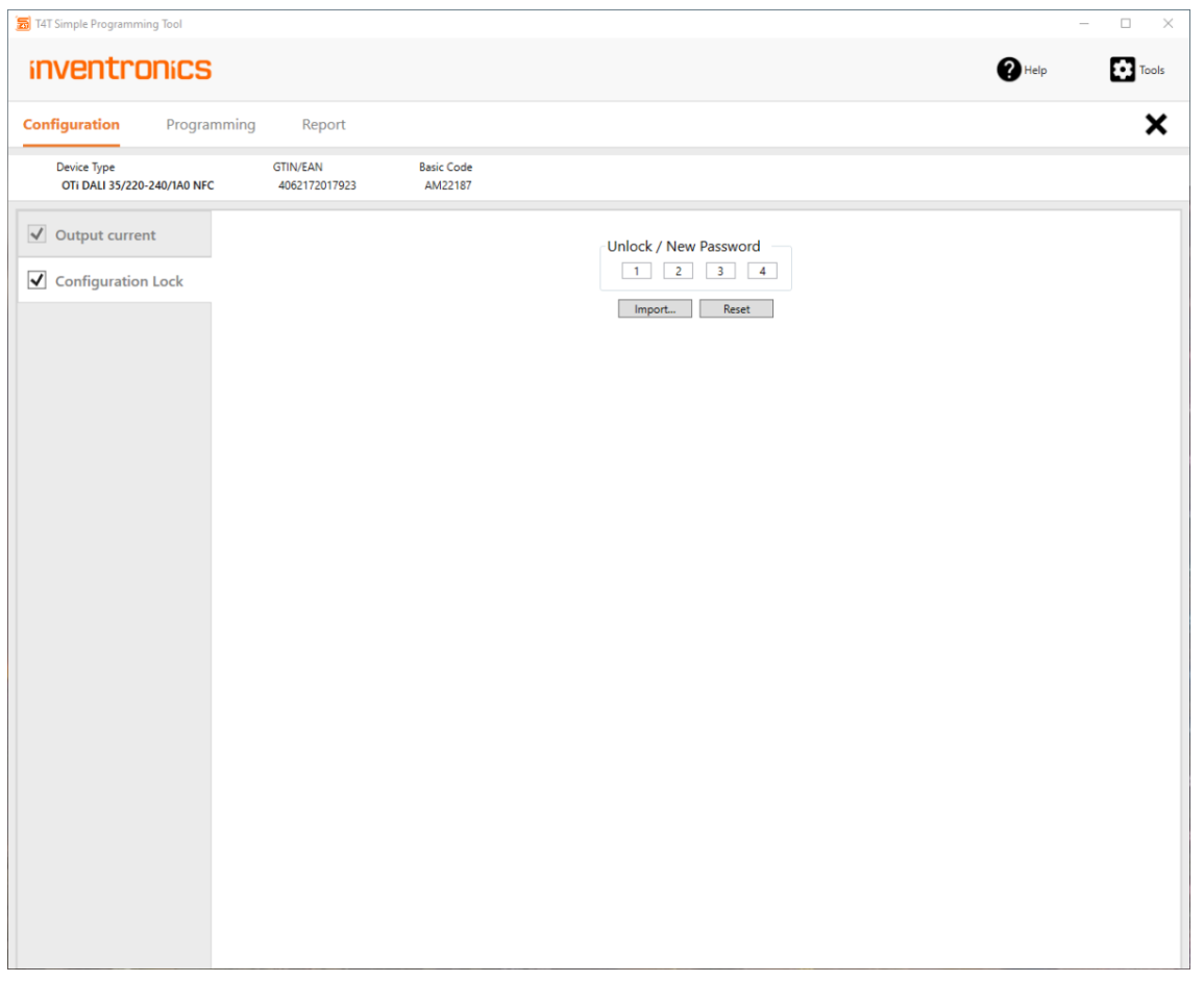
Select the checkbox next to Configuration Lock to protect the driver with a master-key password. If the checkbox is not selected, the driver is not protected. Anyone using the T4T Field app or T4T PC tools with a programming interface may then change the output current and risk overloading the light engine.
Enter the four-digit password manually or import it from an encrypted .osrpwd file. Use Tools > Create PW file to create encrypted password files. An imported encrypted password is displayed as * characters.
Programming a protected driver is rejected if Configuration Lock is not selected or the entered password does not match the driver's password.
Important: Password protection becomes effective after the driver's first power cycle.
2.3 Programming page - programming
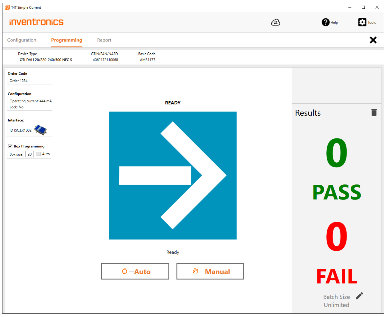
| Area | Description |
|---|---|
| Header | Displays driver data. Programming a driver of a different type from the one shown in the header is rejected. |
| Order Code | Displays the optional order code entered during configuration. |
| Configuration | Shows the data to program: mandatory output current and optional password settings. |
| Interface | Shows the selected programming interface. |
| Box Programming | Enables NFC programming of drivers in a box, when a suitable interface is selected. For drivers released for box programming, Box size is greater than 1 and can be edited. |
| Detected Devices | Shows the number of detected drivers after a programming button is pressed. |
| Status | Shows a status symbol, completion bar and text message. |
| Results | Shows the number of passed and failed programming events. |
Important: DALI addresses are deleted when multiple drivers are connected to the DALI line for batch programming.
Start programming
- Manual: Program the drivers in one luminaire or one box.
- Auto: Start programming when drivers connect to the interface. Automatic mode continues until the batch size is reached. In box programming mode, programming starts when the number of identified drivers matches the box size.
The same driver may be programmed multiple times; only the last pass/fail result is counted. View the programming log on the Report tab.
Use the delete icon to clear the programming report and reset the programming counter. Use the edit icon to change the batch size.
The PDF describes the box-size default, results log and report deletion in terms of a Production File. T4T-S reads a sample driver without requiring a Production File, as explained in section 1.1.
Programming status indicators
| Status | Meaning and action |
|---|---|
| Waiting for Luminaire | Connect a luminaire or driver(s) to start or continue programming. |
| Programming in progress | Do not remove the connected luminaire or drivers until programming is complete. |
| PASS | Programming completed successfully. Remove the luminaire or drivers. |
| FAIL | Programming stopped because of user action or an error. Check the on-screen message, fix the problem and restart programming. |
2.4 Report page
Select Report on the navigation bar to display the report. The PDF describes this as displaying parameters in a Production File; T4T-S itself does not require Production Files.
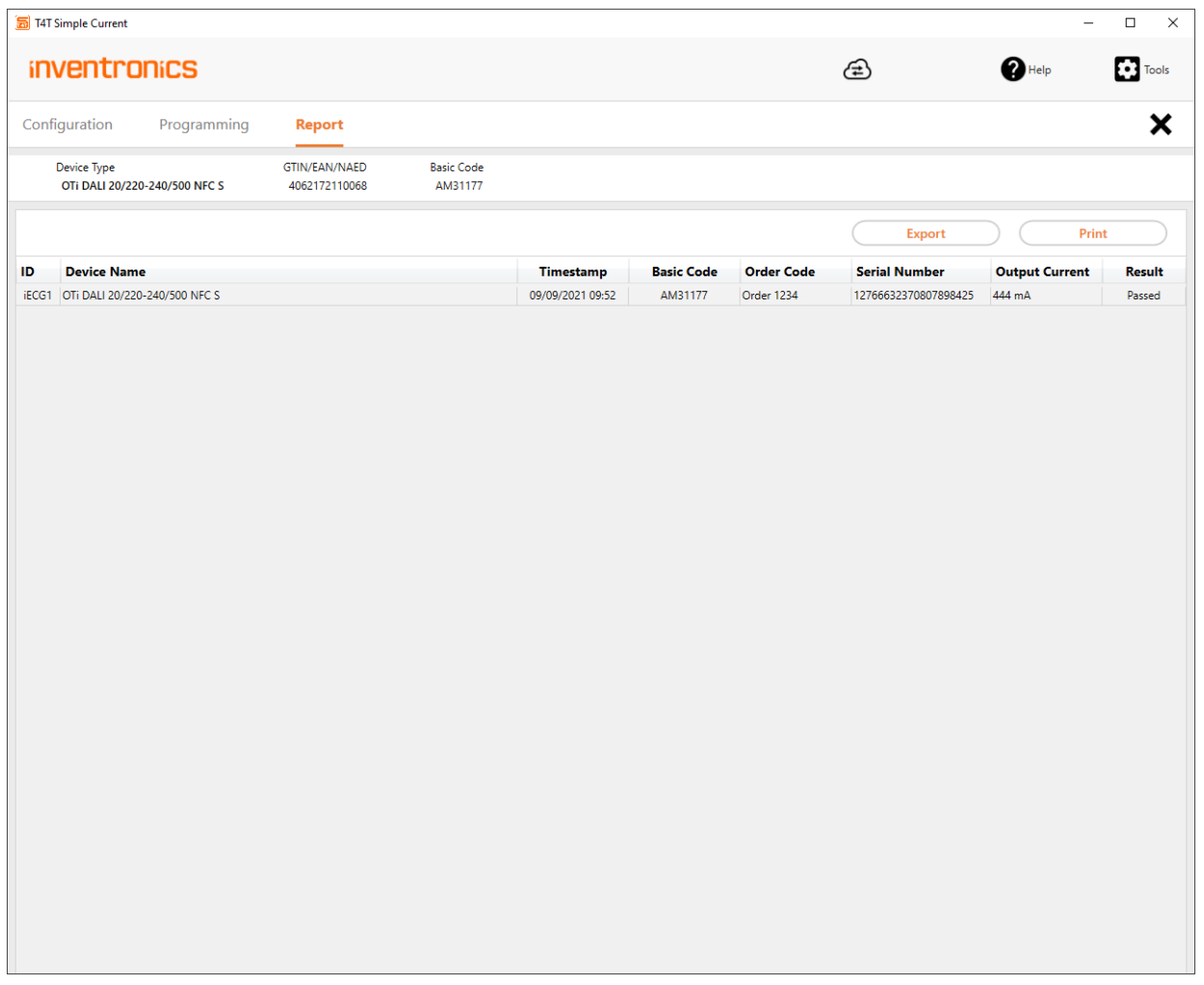
| Control | Function |
|---|---|
| Export | Create an HTML report. Each line represents the programming result for one driver, luminaire or box. |
| Print the report. |
2.5 Tools page
Click Tools and select an entry from the drop-down menu.
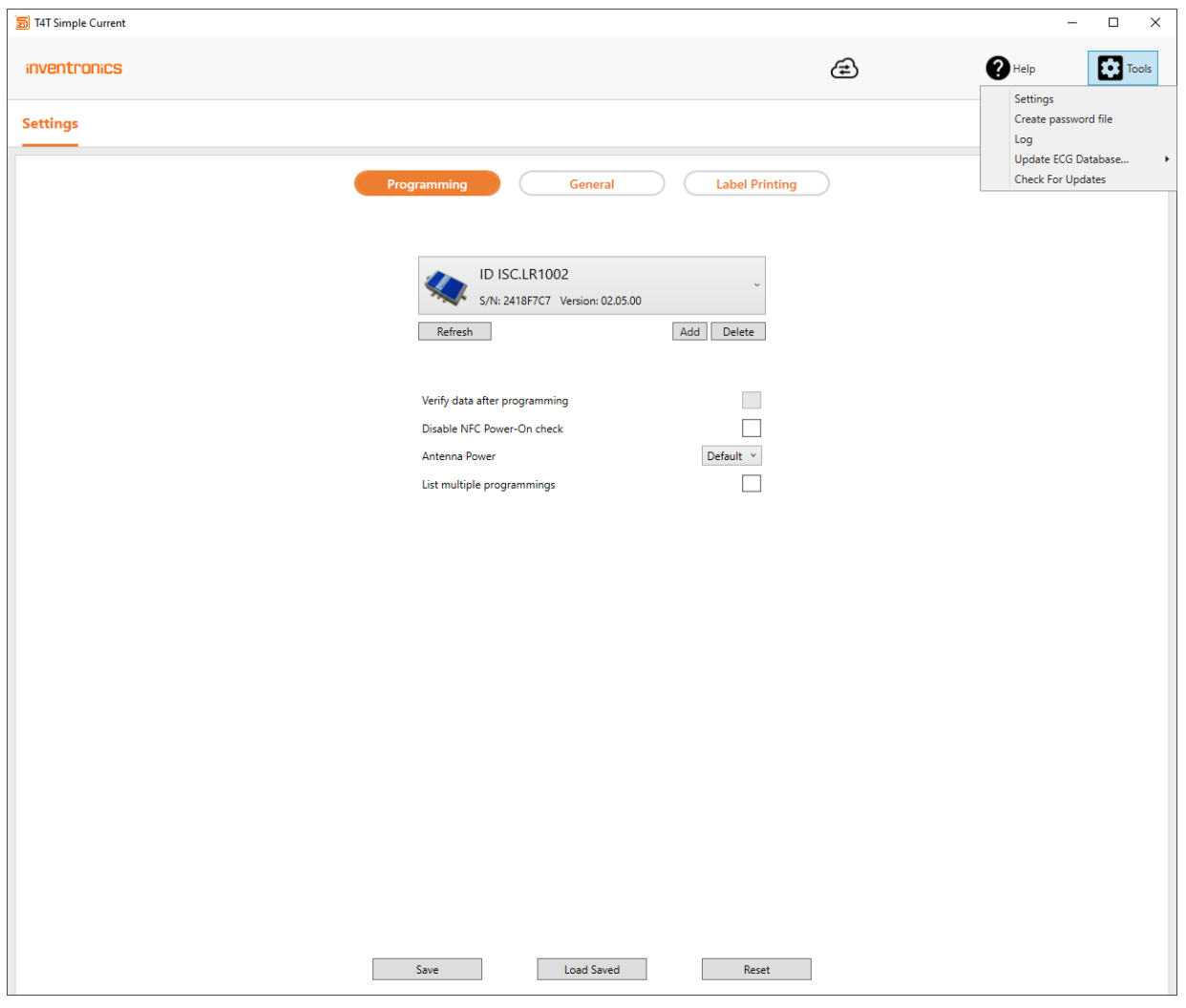
Settings
- Programming: Select the programming interface, verification options and antenna power.
- General: Set language, sound, logging and cloud options.
- Label Printing: Enable label printing.
For details of these settings pages, consult the T4T-P4 user manual, as directed by the source PDF.
Create PW file
Encrypt a password and save it in an encrypted file. You can send the file to the production department for driver programming without disclosing the password.
Log
Display log entries for debugging.
Update ECG database
Update the driver database either by downloading updates from the cloud while online or importing an update file downloaded on another computer from the T4T-S driver database download.
To update the database whenever T4T-S starts, enable Use DriverCloud Service and Check for database updates at startup in General settings. The PDF spells the first option “Use DriverCould Service”.
Important: T4T-S cannot identify new LED drivers if its driver database is outdated.
Check for Updates
Select Check for Updates to check the download center for new T4T-P versions. Updates affect T4T-P4 and T4T-S simultaneously.
Save, Load Saved and Reset
| Control | Function |
|---|---|
| Save | Save options on the local computer and, where applicable, in a Production File. Unsaved changes are ignored when the application restarts; the PDF names T4T-P in this description. |
| Load Saved | Load saved options from the local computer and, where applicable, from a Production File. |
| Reset | Reset options to factory settings and, where applicable, to data from a Production File. |
Service contact
Inventronics GmbH
Parkring 31-33
85748 Garching, Germany
Phone: +49 89 6213-0
www.inventronicsglobal.com
Tuner4TRONIC support: T4Tsupport@inventronicsglobal.com