
4DIM NFC G3 CE LED drivers and T4T-C
Technical application guide for outdoor and industrial LED drivers, current setting, protection, dimming modes, programming, and electrical integration.
Updated · by Administrator
On this page
4DIM NFC G3 CE LED drivers and T4T-C
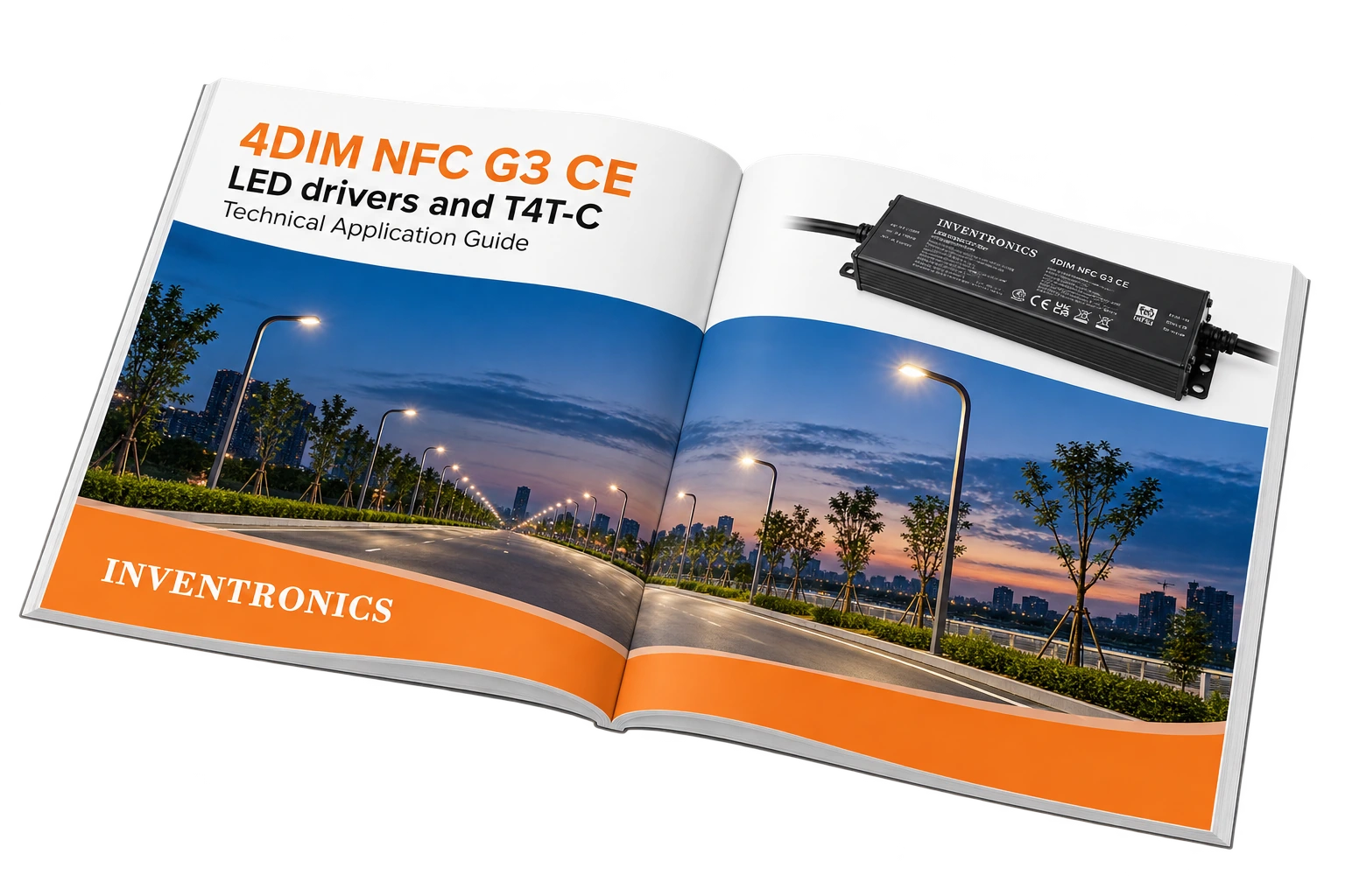
Technical application guide · Inventronics · November 2025
Application Guides · Download source PDF
Source edition: November 2025 (11/25). Product names, software screens, specifications, and contact details reflect that edition. Graphs, wiring diagrams and screenshots preserve their original labels; surrounding instructions are searchable text.
Contents
- 1 Introduction
- 2 Features
- 3 Operating modes
- 4 Additional information
- 5 Programming
- 6 Additional information for electrical design-in
Please note
All information in this guide has been prepared with great care. Inventronics, however, does not accept liability for possible errors, changes and/or omissions. Please check www.inventronics-light.com or contact your sales partner for an updated copy of this guide. This technical application guide is for information purposes only and aims to support you in tackling the challenges and taking full advantage of all opportunities the technology has to offer. Please note that this guide is based on own measurements, tests, specific parameters and assumptions. Individual applications may not be covered and need different handling. Responsibility and testing obligations remain with the luminaire manufacturer/ OEM/application planner.
1 Introduction
1.1 Inventronics LED drivers with 4DIM functionality for outdoor and industrial applications
Long lifetime, low maintenance costs and high efficiency are very important for outdoor and industrial applications. OPTOTRONIC® LED drivers for outdoor applications meet these requirements and unlock the full potential of LED-based light sources.
Thanks to the high flexibility of the programmable OPTOTRONIC® 4DIM NFC G3 CE LED drivers, LED luminaire systems can be optimized to the on-site conditions and cost. With the four integrated dimming functions (4DIM), significant energy saving and a reduction of greenhouse gas emissions can be achieved.
The NFC interface implemented in the 4DIM NFC G3 CE family enables an easy and safe way of programming LED drivers during the production process and also in the field. The parameters can be transferred without the need to power the LED driver, which saves time compared to a programming process using the DALI-2 interface.
Due to the large operating window (voltage/current) of these LED drivers, both Inventronics LED modules for outdoor applications and customer-specific LED modules can be operated. This also means that the overall amount of different LED drivers on stock can be kept low and that the overall complexity of luminaire maintenance over the entire life cycle can be reduced.
The drivers are DALI-2-certified and support stepless dimming, status requests, and addressing of each individual light point. Compared to devices based on DALI version 1, DALI-2-certified drivers ensure a higher interoperability in the system. Moreover, DALI-2 ensures better integration of additional valuable data services thanks to the DALI DATA extensions part -251 (Luminaire Info), part -252 (Energy Reporting) and part -253 (Diagnostic Data).
With the LEDset2 interface, we have created a new path towards standardizing the communication between the LED driver and the LED modules. Without reprogramming, LEDset2 ensures optimal efficiency, a high level of reliability and the adaptability of the LED drivers to the latest LED technologies.
Finally, due to integrated overvoltage protection, LED drivers with 4DIM functionality provide a high level of protection against common mode surges of up to 10 kV for class I and II luminaires.
1.2 4DIM NFC G3 CE product family
The 4DIM NFC G3 CE product family consists of six different output power classes of up to 200 W. The new family consists of ten different types, including variants with a higher output voltage range to enable more and optimized luminaire concepts. All types
have the same 4DIM dimming capabilities and the LEDset2 interface. They can be programmed via the Tuner4TRONIC® software using the DALI-2 or NFC interface. The following overview shows the main features of these LED drivers.
Table 1: Family overview
Product name                      OT  20/170-240/1A0    OT  40/170-240/0A7    OT 40/170-240/1A0     OT 75/170-240/0A7     OT 75/170-240/1A0    OT  75/170-240/1A5
                                  4DIM  NFC  G3 CE      4DIM  NFC  G3 CE      4DIM  NFC  G3 CE      4DIM  NFC G3  CE      4DIM NFC  G3 CE      4DIM  NFC  G3 CE
General
Maximum   power                    22 W                  40 W                 40 W                  75 W                  75 W                  75 W
Input voltage L/N                  220–240  V            220–240 V            220–240  V            220–240  V            220–240  V            220–240  V
Nominal output voltage             10–38 V               30-77 V              15–56  V              50–150  V             35–115 V              25–75V
Output current range               1050 mA               700 mA               1050 mA               700 mA                1050 mA               1500 mA
Surge (dif/com)                    6/10 kV               6/10 kV              6/10 kV               6/10 kV               6/10 kV               6/10 kV
DA-DA  Surge                       1 kV                  1 kV                 1 kV                  1 kV                  1 kV                  1 kV
DALI-PE                            8 kV                  8 kV                 8 kV                  8 kV                  8 kV                  8 kV
Insulation
(primary/secondary)
                                   SELV                  SELV                 SELV                  Double                SELV                  SELV
Insulation of casing
                                   Double                Double               Double                Double                Double                Double
Stand-by power                     < 0.5 W               < 0.5 W              <  0.5 W              < 0.5 W               < 0.5 W               < 0.5 W
Table    2: Family     overview
Product name                      OT  110/170-240/0A7   OT 110/170-240/1A0    OT 165/170-40/1A0     OT 200/170-40/1A0
                                  4DIM  NFC  G3 CE      4DIM  NFC  G3 CE      4DIM  NFC G3  CE      4DIM NFC  G3 CE
General
Maximum   power                    110 W                 110 W                165 W                 200 W
Input voltage L/N                  220–240 V             220–240 V            220–240  V            220–240  V
Nominal                            80–220 V              55–157 V             90–260  V             140–300  V
output voltage
Output                             700 mA                1050 mA              1050 mA               1500 mA
current range
Surge (dif/com)                    6/10 kV               6/10 kV              6/10 kV               6/10 kV
DA-DA  Surge                       1 kV                  1 kV                 1 kV                  1 kV
DALI-PE                            8 kV                  8 kV                 8 kV                  8 kV
Insulation
(primary/secondary)
                                   Double                Double               Double                Double
Insulation of casing
                                   Double                Double               Double                Double
Stand-by power                     < 0.5 W               < 0.5 W              < 0.5 W               < 0.5 W
It is possible to operate the driver below the minimum nominal current through initial setting of the output current.
Warning:
When LED drivers are permanently operated below the minimum nominal current, it is necessary to ensure compliance with relevant IEC standards (for example, mains current distortion and power factor). Please consider that the certificates are only valid within the nominal output current range.
DALI-2
In this operating mode, the driver can be controlled by a DALI application controller via the bidirectional DALI interface and it supports status queries. Through the application controller, the driver can be integrated into a light management system.
The drivers are DALI-2-certified and support stepless dimming, status requests, and addressing of each individual light point. Compared to devices based on DALI version 1, DALI-2-certified drivers ensure more functions and a higher interoperability in the system.
StepDIM/StepDIM inverse
Dimming via an external control phase: Predefined dimming levels can be varied via the Tuner4TRONIC® software and the polarity of the phase. The SD2 port also allows control via a mains-powered presence sensor.
AstroDIM/presence detection
Automatic dimming via an integrated timer (no real-time clock): Five independent dimming levels and zones can be set with the Tuner4TRONIC® software. Brightness variation is possible in combination with an external presence sensor.
MainsDIM
Dimming via mains voltage amplitude: This feature is often used in combination with magnetic ballasts in outdoor applications. The dimming behavior can be set via the Tuner4TRONIC® software.
CLO (constant lumen output)
The decrease in the luminous flux of an LED module can be compensated over its entire lifetime via a preprogrammed current curve. This not only ensures stable lighting, but also saves energy and increases the lifetime of the LEDs.
Monitoring Data
LED drivers with this feature offer additional operation and status information according to the DALI-2 DATA extensions (parts -251, -252 and -253), such as energy consumption, power, operating time, overvoltage or undervoltage etc. By using these data, it is possible to offer predictive maintenance and an overall better lighting service. Moreover, it makes the light management system intelligent.
The data can also be visualized in the Tuner4TRONIC® software.
LEDset
LEDset is an improved LED module interface for the combination of single or multiple LED modules with one LED driver via a single analog control line. This interface enables external current setting and temperature monitoring. The LEDset2 interface has no auxiliary supply and is not compatible with LEDset (Generation 1). LEDset2 has an absolute current coding, while LEDset (Generation 1) only has a relative one. In the 4DIM NFC G3, LEDset and NTC functionality share the same connection terminal. Both features are not simultaneously available. — LEDset functionalities are limited only to the current setting (via codified resistor) and to thermal protection via PTC (5 V supply, miswiring protection, thermal protection with NTC are not available).
External temperature sensor
This feature allows the temperature protection of the LED module or the complete luminaire in hot ambient temperatures via an external sensor (e.g. NTC, negative temperature coefficient resistor). The derating can be modified via the Tuner4TRONIC® software.
Integrated overvoltage protection
The 4DIM CE drivers have an integrated overvoltage protection of up to 6 kV for differential and 10 kV for commonmode overvoltages.
Configuration Lock
Configuration Lock This feature is an advancement of OEM Key, which allows controlling the access rights for individual features within the LED driver via Tuner4TRONIC® software and assigning different rights to the luminaire manufacturer, to the service team and to the general user. Assigning user rights also allows offering “light as a service” and still maintaining total control over who may change what within the device or luminaire.
Tuning Factor
Tuning Factor Within limits predefined by the luminaire manufacturer, this feature allows an adjustment of the amount of light in the field or in production. Thus, one luminaire can manage different lumen packages. If the feature is combined with LEDset, other lumen packages can also be achieved, which differ in terms of resistor coding.
Driver Guard T, P
By default, the internal protection mechanisms of the LED driver are designed for maximum performance and temperature, however, not for those of the luminaire. By means of this feature, the performance and temperature derating of the LED driver can be adjusted according to the luminaire performance, thus maximizing the reliability of the system.
1.3 Nomenclature
The product name of each OPTOTRONIC® 4DIM CE LED driver is defined as shown below.
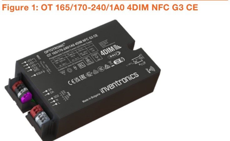
OT: OPTOTRONIC® LED driver 165: Power class: 165 W 170-240: Input voltage range (L/N): 170-240 V 1A0: Max. output current: 1050 mA 4DIM: 4DIM functionality (DALI, StepDIM, AstroDIM, MainsDIM) NFC: NFC for LED driver programming G3: Generation 3 C: Compact housing shape E: For exterior use under specific conditions
1.4 Operating windows
The OPTOTRONIC® 4DIM NFC G3 CE LED driver family is split up into six different power classes to provide the best suitable power supply for different applications. The nominal output current of 150-1050 mA (1500 mA for 1 version) is available in the following power packages.
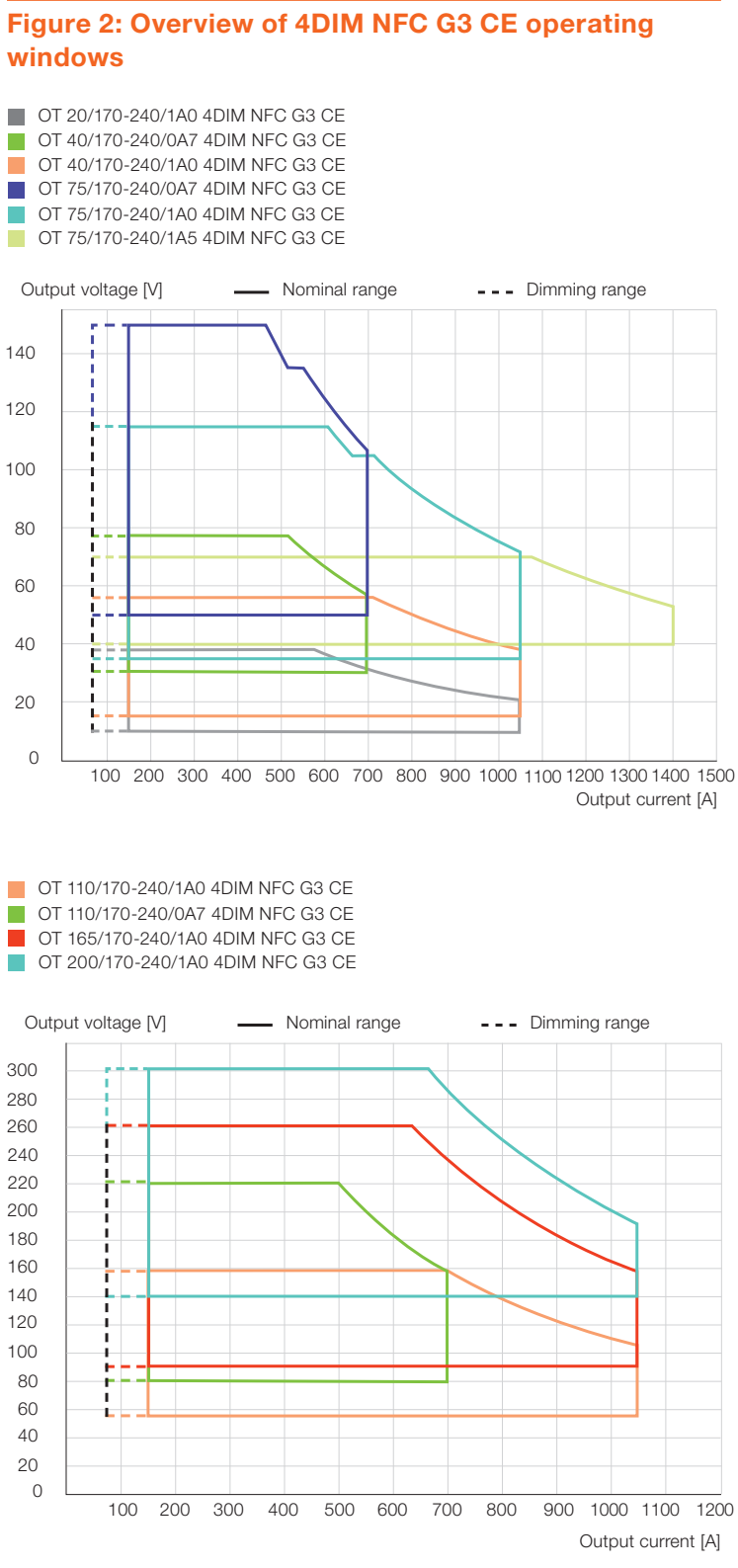
Table    3: 4DIM     NFC    G3   CE   operating       range
Type          OT 20/170-     OT 40/170-     OT 40/170-     OT 75/170-     OT 75/170-     OT 75/170-     OT  110/170-    OT 110/170-    OT 165/170-    OT 200/170-
              240/1A0 4DIM   240/0A7  4DIM  240/1A0  4DIM  240/0A7  4DIM  240/1A0  4DIM  240/1A5  4DIM  240/0A7  4DIM   240/1A0 4DIM   240/1A0  4DIM  240/1A0  4DIM
              NFC G3 CE      NFC G3  CE     NFC  G3 CE     NFC  G3 CE     NFC G3 CE      NFC  G3 CE     NFC  G3 CE      NFC G3 CE      NFC G3  CE     NFC  G3 CE
P             22 W           40 W           40 W           75W            75 W 1)        75W            110 W           110 W 1)       165 W 1)       200 W
 max
t             -40 ...+60 °C  -40 ...+60 °C  -40 ...+60 °C  -40…+55  °C    -40 ...+55 °C  -40…+60  °C    -40…+55  °C     -40 ...+55 °C  -40 ...+55 °C  -40…+55  °C
 a
V
 in           220–240 V      220–240 V      220–240  V     220–240V       220–240 V      220–240V       220–240V        220–240 V      220–240  V     220-240V
(nominal)              AC              AC             AC                            AC                                           AC              AC             AC
Minimum
dimming       70 mA          70 mA          70 mA          70 mA          70 mA          70 mA          70 mA           70 mA          70 mA          70 mA
current
Minimum
nominal       150 mA         150 mA         150 mA         150 mA         150 mA         350 mA         150 mA          150 mA         150 mA         150 mA
current
Maximum
nominal       1050 mA        700 mA         1050 mA        700 mA         1050 mA        1500 mA        700 mA          1050 mA        1050 mA        1050  mA
current
Minimum
output        10 V           30 V           15 V           50 V           35 V           25 V           80 V            55 V           90 V           140 V
voltage
Maximum
output        38 V           77 V           56 V           150 V          115 V          75 V           220 V           157 V          260 V          300 V
voltage
1) At input voltages  below   190 V, the driver protects  itself, as shown   in figure 4.
It is possible   to  operate    the  driver   below   the   minimum      nominal    current    through    initial setting   of the  output    current.
Warning:
When LED drivers are permanently operated below the minimum nominal current, it is necessary to ensure compliance with relevant IEC standards (for example mains current distortion and power factor). Please consider that the certificates are only valid within the nominal output current range.
1.4.1 Current foldback
The intelligent 4DIM NFC G3 family allows a safe start-up of the system, even if the power consumption or the total forward voltage of the LED module exceeds the maximum output power or voltage of the LED driver. In this case, the unit reduces the current until the maximum output voltage [1] or power [2] is not exceeded anymore. If no stable operating point is achieved, the unit switches on and off continuously or switches off completely.
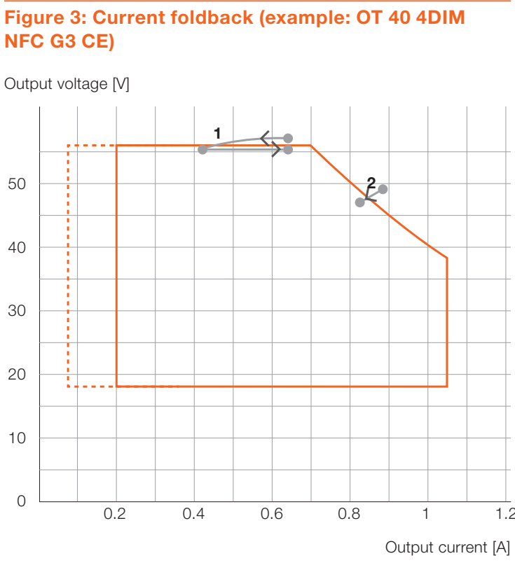
Please note:
At ambient temperatures below -25 °C, the LED driver supplies 200 mA for a maximum of 1 minute to warm up, and after this, it supplies the programmed output current.
1.4.2 Low input voltage protection
In case of a very low input voltage, the driver protects itself against being damaged by high input currents. The behavior of the driver can be seen in figure 4.
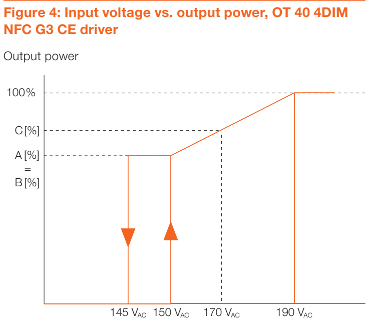
Mains voltage
A [%] = B [%] C [%] OT 20/170-240/1A0 40 40 75 4DIM NFC G3 CE OT 40/170-240/XXX 68 68 85 4DIM NFC G3 CE OT 75/170-240/XXX 70 70 85 4DIM NFC G3 CE OT 110/170-240/XXX 70 70 85 4DIM NFC G3 CE OT 165/170-240/1A0 50 50 75 4DIM NFC G3 CE OT 200/170-240/1A0 50 50 75 4DIM NFC G3 CE
2 Features
2.1 Operating current
Flexible current setting allows taking advantage of the continuously improving LED technology and building a future-proof system. The 4DIM NFC G3 family offers two modes for current setting, which can be set via the Tuner4TRONIC® software: — Fixed current: Current setting via programmable interface — LEDset2: Current setting via the LEDset2 interface
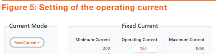
Without any resistor connected to the LEDset2 interface, the factory default current is 700 mA. As soon as the LED driver detects a resistor value for more than 3 seconds within the valid resistor range (see table 4), it switches to the LEDset2 mode.
2.1.1 Fixed current mode
To use the fixed current mode, it has to be selected in the Tuner4TRONIC® software. The minimum and maximum ra ted output currents are displayed according to the selected LED driver. The output current of the LED driver can be set by changing the value in the “Operating Current” field.
2.1.2 LEDset2 mode
The LEDset2 interface (LEDset generation 2) is a s tan dardized LED module interface to set the right output current and establish an easy and low-cost temperature protection for the connected LED module. This multi-vendor interface is suitable for LED modules connected in parallel or in series.
Note:
In the following figures, the LED module is displayed in a simplified way. The real number of LEDs depends on the output voltage of the driver.
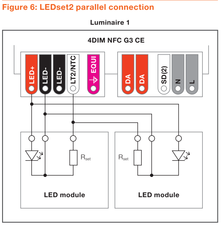
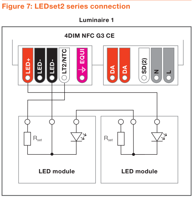
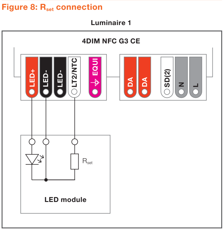
The output current of the LED driver can be set using an externally connected resistor (min. power rating 50 mW, max. tolerance 0.5 %). This provides the possibility to set the LED current manually without the need for an additional programming of the LED driver. With a resistor mounted on the LED module, as shown in figure 8, the correct LED current can be set automatically. With this resistor, the desired current for the LED module is set according to the used LED bin and needed lumen output, offering a real plugand-play solution and making the system future-proof.
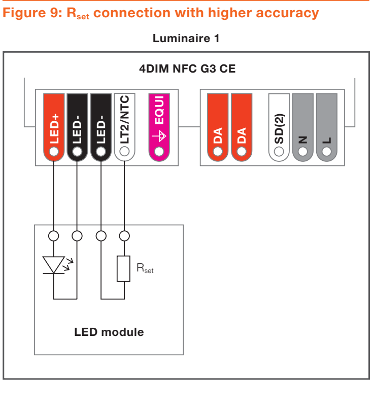
To achieve a more accurate current setting, the second LEDterminal of the LED driver can be used as shown in figure 9. This increases the accuracy by roughly 0.5 %.
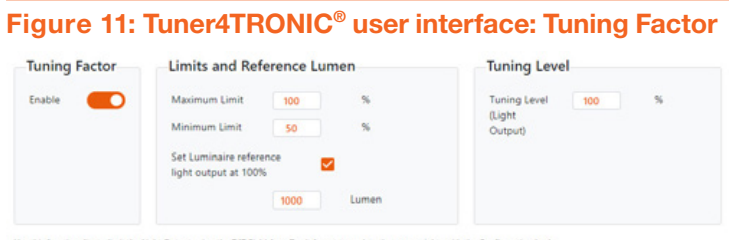
Maximum limit: This is the maximum operating current set by the luminaire manufacturer. It is equivalent to 100 %.
Minimum limit: This is the minimum definable output current level. Valid range: 50–100 %.
Luminaire reference light output: This value indicates a reference light output of the luminaire at 100 % output current. This enables the installer to easily adjust the light output in lumen instead of the output current.
Tuning level: This is the current tuning level set by the installer.
The “limits and reference lumen” can be independently protected by the Configuration Lock feature in order to avoid unauthorized usage of this feature outside the limits defined by the luminaire manufacturer.
2.2 Thermal derating and protection
2.2.1 External temperature sensor
By connecting an external temperature sensor to the NTCset port of the 4DIM NFC G3 CE LED driver, a very easy and cost-efficient temperature protection of the LED module can be realized. As an example, an NTC (negative temperature coefficient resistor) can be mounted on the LED module and connected as shown in figure 12. In case the thermal protection feature is enabled and nothing is connected to the NTCset terminal, the driver delivers 100 % light output.
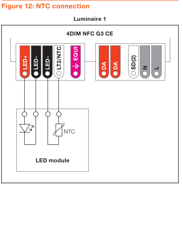
Resistor-based mode The resistor-based mode is activated by default. If the connected resistor sensor value falls in the range between 6.3 and 5.0 kΩ, the output current is continuously lowered down to 50 %. If the value falls further below 4.3 kΩ, the output is switched off completely until the sensor reaches 5.0 kΩ again. The complete switch-off can be deactivated by clicking on the “Shut Off” check box.
In this mode, a common NTC can be used to achieve a fixed thermal protection, as shown in table 5. The specified temperatures can vary, depending on the used NTC component and the corresponding tolerances.
Table 5: Overview of standard NTCs
NTC type Start derating End derating Shut-off temperature temperature 1) temperature [6.3 kΩ] [5.0 kΩ] [4.3 kΩ]
22 kΩ           56 °C                62  °C                67 °C
33 kΩ           66 °C                72  °C                77 °C
47 kΩ           75 °C                83  °C                87 °C
68 kΩ           85 °C                92  °C                97 °C
1) Switch-on   temperature   in case  the temperature    has  reached   the
  shut-off  condition
2.2.2 Thermal management and Driver Guard feature
The 4DIM NFC G3 CE LED driver family has a reversible internal thermal protection. If the maximum allowed LED driver temperature is exceeded, the LED driver starts derating the output current down to 55 %. If the temperature keeps increasing, the LED driver switches off. It switches back on at the maximum allowed temperature.
In outdoor installations especially, the lifetime and reliability of a luminaire is very important. As the lifetime of a luminaire always depends on the operating temperature of the components, the “Driver Guard” feature helps limiting the LED driver’s temperature during its operation. The thermal behavior of the LED driver can be activated at lower temperatures using the “Prestart Derating” setting shown in the figure below.
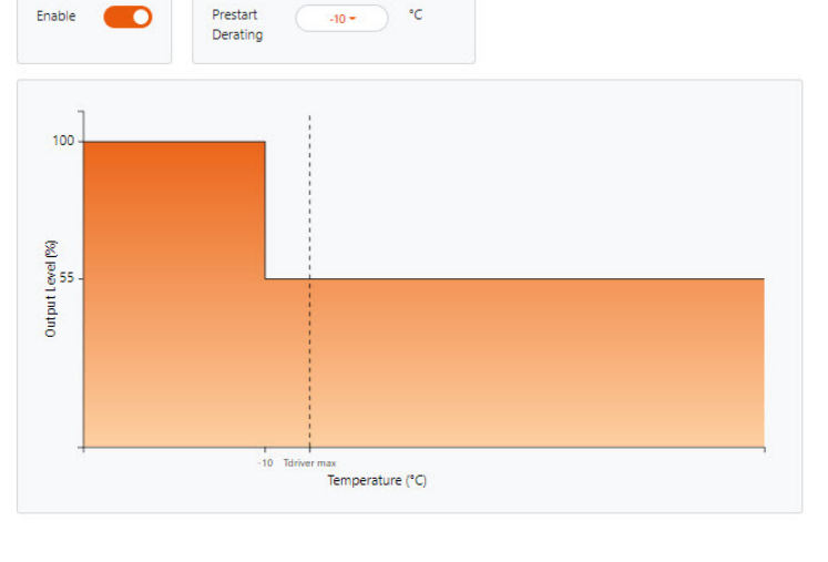
Note:
The luminaire manufacturer is responsible for the proper thermal design of the luminaire. The temperature indicated in this feature might significantly differ from the t temperac ture mentioned on the top of the LED driver. To achieve the lifetime data of the LED driver, the luminaire manufacturer needs to ensure that the maximum t temperature is never c exceeded.
2.3 Constant Lumen function
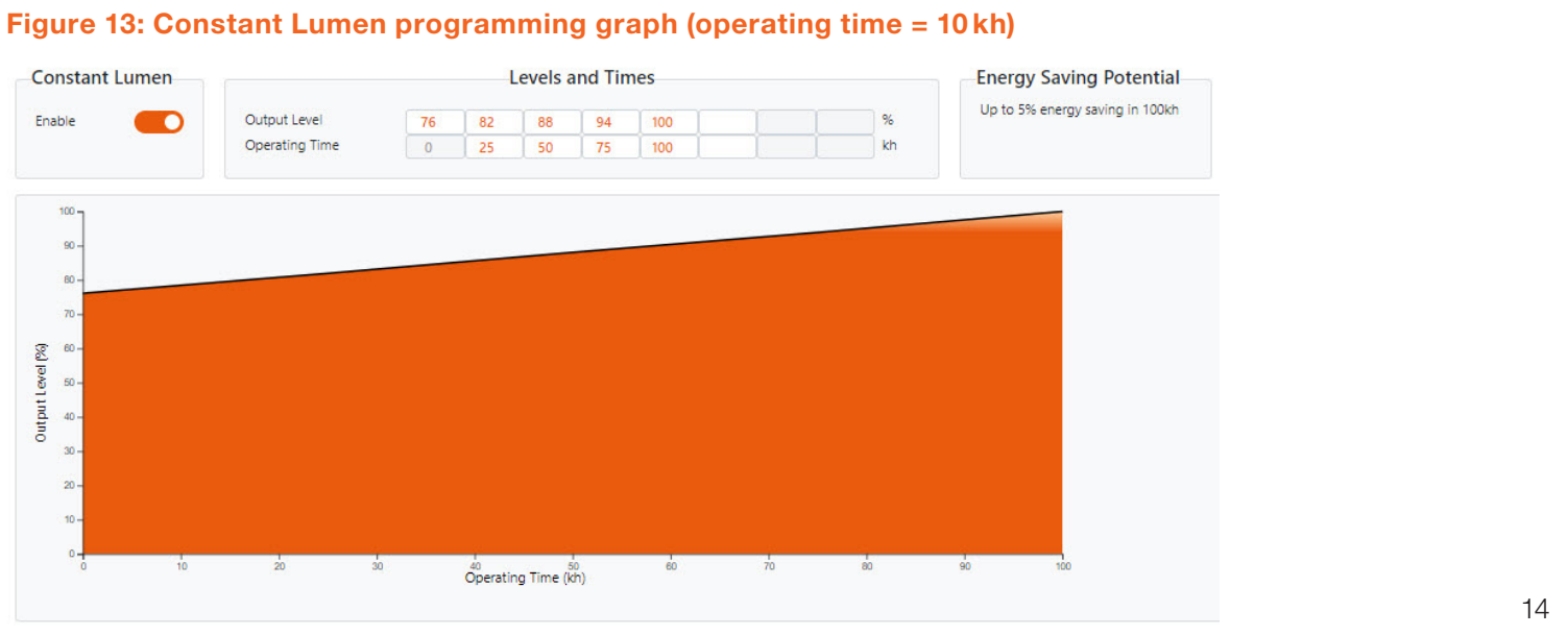
Over the lifetime of an LED module, the light output drops due to the aging process of the LEDs. To achieve a constant light output of the module, the LED driver stores the operating hours of the LED module and increases the output current to react to the light output drop. To set this feature according to the applied LED module, the T uner4TRONIC® software can be used as shown, for example, in figure 13.
The output levels have to be steadily increasing from the beginning to the end.
The output level cannot fall below the minimum physical dimming level of the LED driver, even if the software displays a lower value.
Next to the table, the estimated energy savings are calculated as shown in figure 13. This value is only an estimation because it does not consider, for example, the LED V bef havior and the efficiency of the driver.
The exact values for programming the Constant Lumen function for the connected LED module need to be obtained from the corresponding LED or LED module supplier.
2.4 Lamp operating time
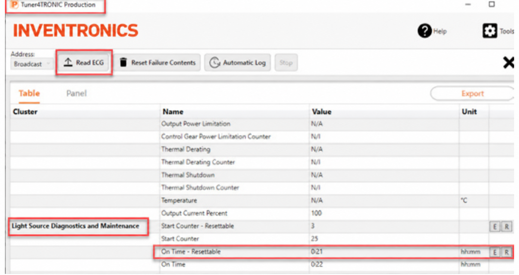
The LED driver monitors the operating hours of the connected LED module. In case of a fault of the LED driver or module, the lamp operating time has to be (re)set accordingly with the Tuner4TRONIC® software. The lamp operating time also has an influence on the Constant Lumen function and the “end of life” feature. It can be set using the Tuner4TRONIC® software, as shown in figure 14.
Figure 14: Lamp operating time (10 kh)
The actual lamp operating time can be displayed and edited in the feature tab "Operating Time for ECGs without M onitoring Data".

Lamp operating time allows the display and editing of the actual on-time of the LED module, which is the basis for the CLO (constant lumen output) profile. Drivers that feature monitoring data (DiiA: DALI part -253) use “Light Source Diagnostics and Maintenance: On Time – Resettable” to display elapsed time for CLO. “On-Time – Resettable” can be edited by reading Monitoring Data from drivers with T4T-P4.
2.5 End of life
The LED driver can indicate that a preprogrammed lifetime of the connected LED module is reached and the module should be replaced. This function has to be activated in advance via the Tuner4TRONIC® software. The “end of life” indication can be programmed as shown in figure 15.
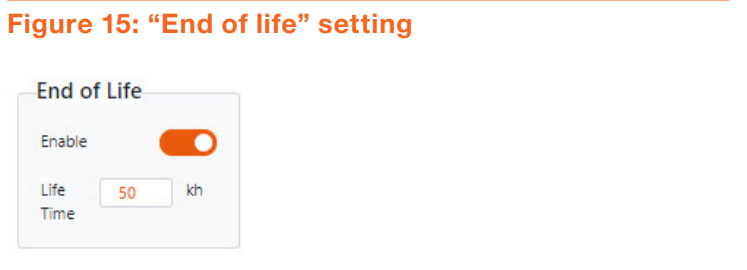
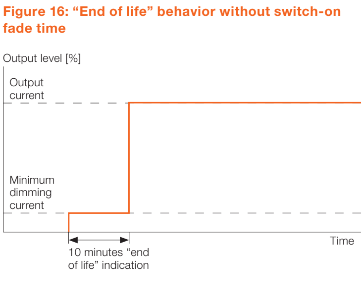
If the specified lifetime is reached, the LED driver indicates this through a lower light output during the first 10 minutes of the switch-on period, as shown in figure 16.
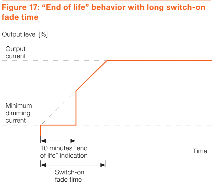
If a switch-on fade time is set, it is overridden by the “end of life” functionality, as shown in figure 17. After 10 minutes, the output current is set according to the current switch-on fade time level.
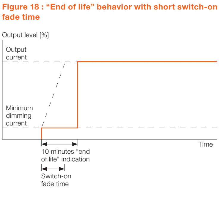
If the switch-on fade time is shorter than 10 minutes, the output current is directly switched to the nominal output level after the “end of life” indication, as shown in figure 18.
Note:
In DC operation, the “end of life” indication is deactivated until the next power-on/off cycle or DALI operation.
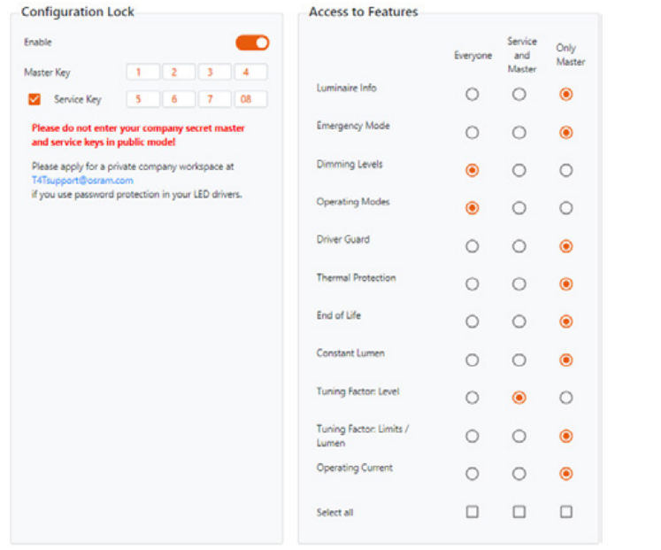
2.6 Configuration Lock
The protection of the LED driver settings is mandatory to guarantee a safe operation of a luminaire over its entire lifetime. In order to meet growing market demands to change settings of a luminaire in the field, we developed a new Configuration Lock, allowing a safe operation of the luminaire while also giving the end customers the possibility to adapt the settings of the luminaire in the field. With this approach, the luminaire manufacturer keeps the complete control over the boundaries that define how his product will be operated.
Example 1: The luminaire manufacturer locks all settings, no in-field changes possible.
The luminaire manufacturer sets a “Master Key” and locks all the features. Without knowing the programmed “Master Key,” nobody can change the LED driver settings anymore. Features can be kept unlocked by selecting “Everyone” in the corresponding line.
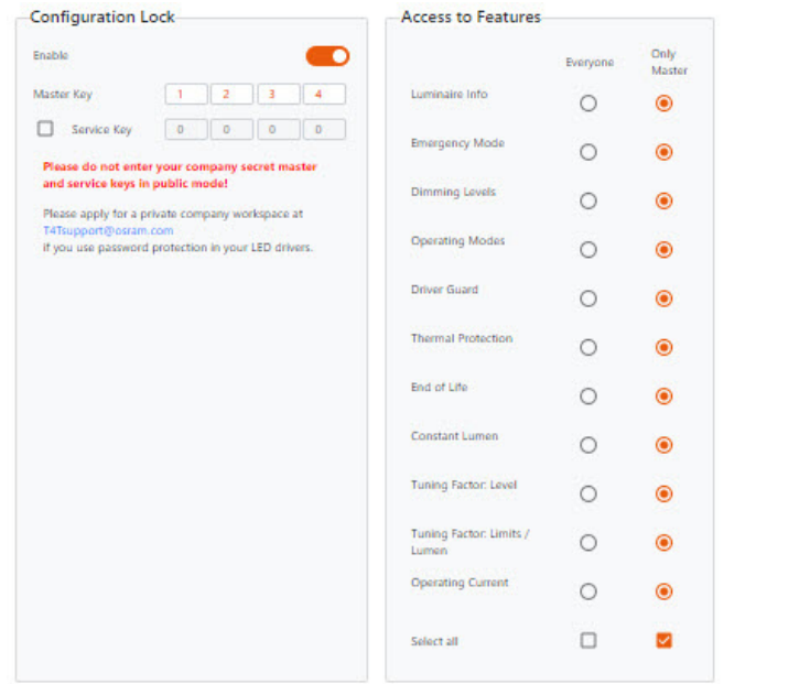
Example 2: The luminaire manufacturer defines boundary conditions and enables in-field programming.
The luminaire manufacturer defines his “Master Key” and keeps the full access rights to the settings of the LED driver. An additional “Service Key” can be set to allow people knowing this key to adapt the corresponding feature(s) of the LED driver.
In this example, people who received the “Service Key” (e.g. service personnel) can change the light output of the luminaire using the tuning factor level. As the “Limits and Reference Lumen” of the Tuning Factor feature is locked, the user can only adapt the light output within the limits defined by the luminaire manufacturer. In this case, all settings related to operating modes and AstroDIM can be changed.
3 Operating modes
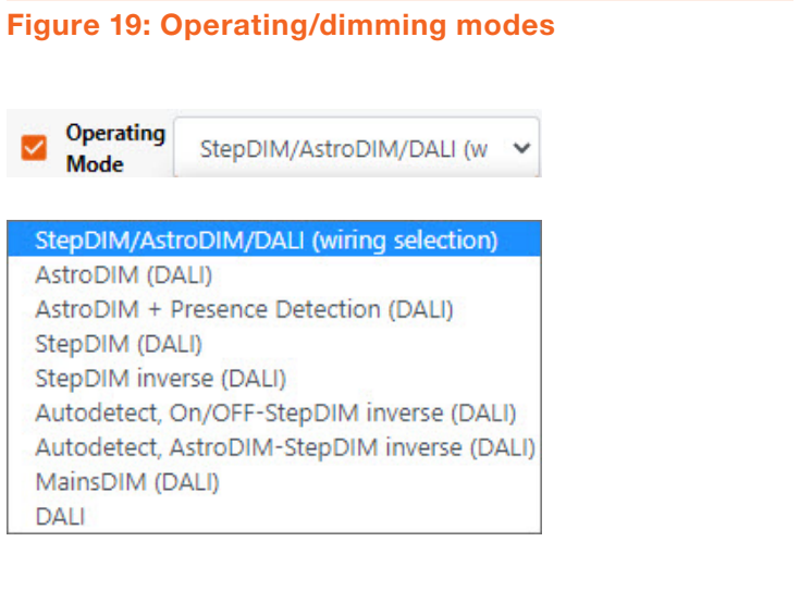
The operating modes of a 4DIM NFC G3 CE LED driver can be selected using the Tuner4TRONIC® software. Only one mode can be selected.
Note:
DALI always has a higher priority than the selected operating mode and can be activated by a valid DALI command in every mode. After a power-off/on cycle, the LED driver operates in the originally selected dimming mode again.
The LED driver offers the possibility to select one of the two dimming modes “StepDIM (DALI)” or “AstroDIM (DALI)” via external wiring in case the default dimming mode “StepDIM/AstroDIM/DALI (wiring selection)” is set. Please see chapter 3.2.1 for wiring information.
3.1 On/off operating mode
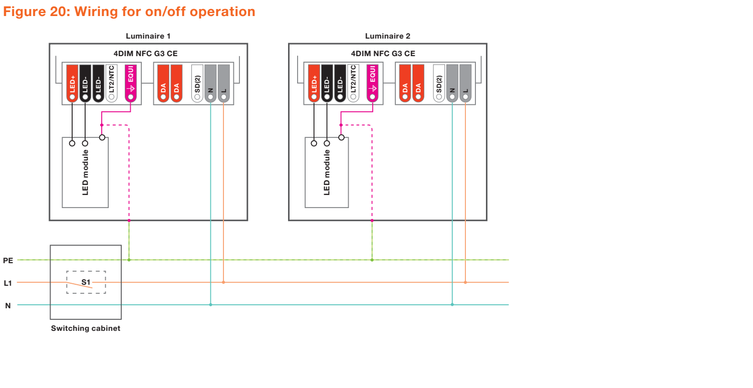
4DIM NFC G3 CE LED drivers can also be used in a simple on/off operating mode. One of the following dimming modes needs to be selected:
— StepDIM/AstroDIM/DALI (wiring selection) – DALI and SD(2) port not connected — StepDIM (DALI) – DALI and SD(2) port not connected — DALI – DALI port not connected
Note:
Be aware that the parameters set in these operating modes also have an influence on the behavior of the LED driver in the on/off operating mode.
3.2 AstroDIM feature
The AstroDIM feature allows an autonomous dimming without the need for an additional control line. The 4DIM NFC G3 CE LED drivers support up to five independent dimming levels and flexible settings of fade times between the individual dimming levels.
The output levels can be set to 0 % (OFF) or between 10 % and 100 % in steps of 1 %.
In addition, switch-on and switch-off fade times can be programmed at the beginning and the end of a switching cycle to allow for further energy savings during the twilight phase. This function is also helpful for installations with a pedestrian crossing where no specific infrastructure is available to switch the pedestrian crossing illumination independently of the rest of the street light illumination.
Two different modes for AstroDIM are supported:

T ime-based: The dimming profile defined in the reference schedule is referenced to the switch-on time of the LED driver.
A stro-based: The dimming profile defined in the reference schedule is referenced to the annual average middle of the night, which is calculated based on the theoretical sunrise and sunset times.
The LED driver does not have a real-time clock. The internal reference clock is derived from the mains frequency and the driver detects if it is connected to a 50 Hz or 60 Hz supply system, assuming a time base of 20 ms or 16.6 ms. This allows a synchronized switching of all units. In case of DC operation (see chapter 3.6), the dimming mode is stopped until the AC voltage is applied again and a poweroff/on cycle is performed.
Warning:
If the output level is set below the minimum physical dimming level of the LED driver (except OFF), the minimum dimming current is used. The software still displays the original value. If the output level falls below the minimum allowed dimming current, the value is visualized in red.
3.2.1 Wiring and feature activation
There are two ways to activate the AstroDIM mode:
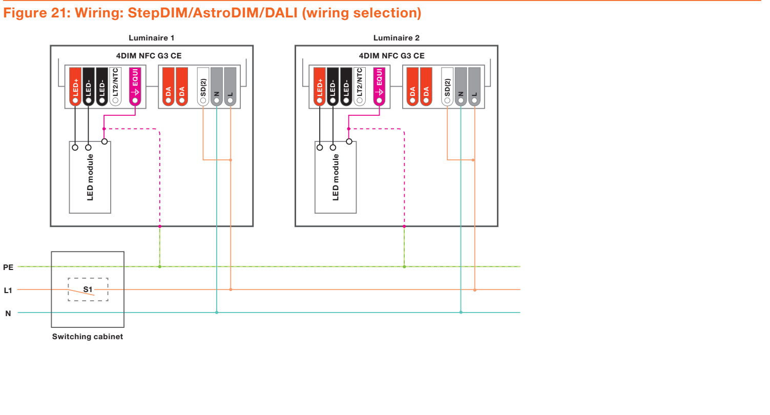
— Option 1: By external wiring Selected dimming mode (factory default): “StepDIM/AstroDIM/DALI (wiring selection)” — Option 2: Via the Tuner4TRONIC® software Selected dimming mode: “AstroDIM (DALI)” or “AstroDIM PD (DALI)”
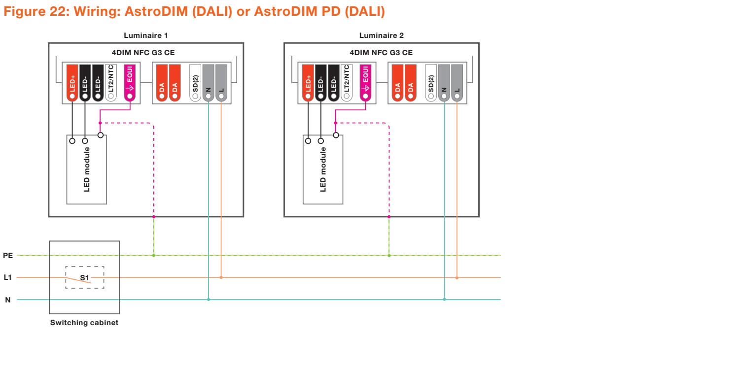
For option 1, the AstroDIM feature is activated without the need for programming. Only a permanent connection between the L and the SD(2) port of the LED driver is necessary (see figure 21). If the SD(2) port is not active during the start-up phase of the LED driver (for 1 s), the StepDIM feature is activated instead of the AstroDIM feature. Information on the default dimming profile can be found in the datasheet of the applied LED driver.
For option 2, the external wiring can be avoided if either the “AstroDIM (DALI)” or “AstroDIM PD (DALI)” dimming mode is selected via the software (see figure 22).
3.2.2 Time-based mode
In this mode, the LED driver performs the dimming profile defined in the reference schedule based on the switch-on time of the unit. Five independent output levels can be set for each step. The minimum length of one dimming period has to be longer than the AstroDIM fade time.
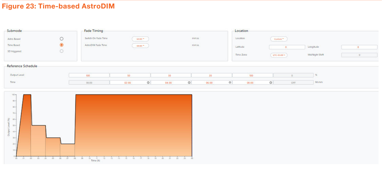
Fade timing: — AstroDIM fade time: Fade time between the different dimming levels. — Switch-on fade time: Fade time after the power-on of the LED driver. The output level at the end of this fade time is defined by the output level of the corresponding dimming period.
The maximum duration of the schedule is 23 h and 59 min. If less than five output levels need to be performed, two sequenced levels have to be set to the same value. The AstroDIM dimming profile in the time-based mode already starts after the first power-off/on cycle after programming.
Table 6: Fade timing parameters (time-based mode)
Parameter                    Min.              Max.             Default
AstroDIM   fade  time        0, 2 s            8 min            3 min
Switch-on   fade  time       0, 15 s           60 min           0 s
3.2.3 Astro-based mode
In this mode, the LED driver performs a dimming profile based on the daily power-on and power-off times. The dimming schedule is adapted according to the length of the night.
The Tuner4TRONIC® software calculates the annual average middle of the night based on the theoretical sunrise and sunset times, which are related to the location selected in the software. Based on this average middle of the night,
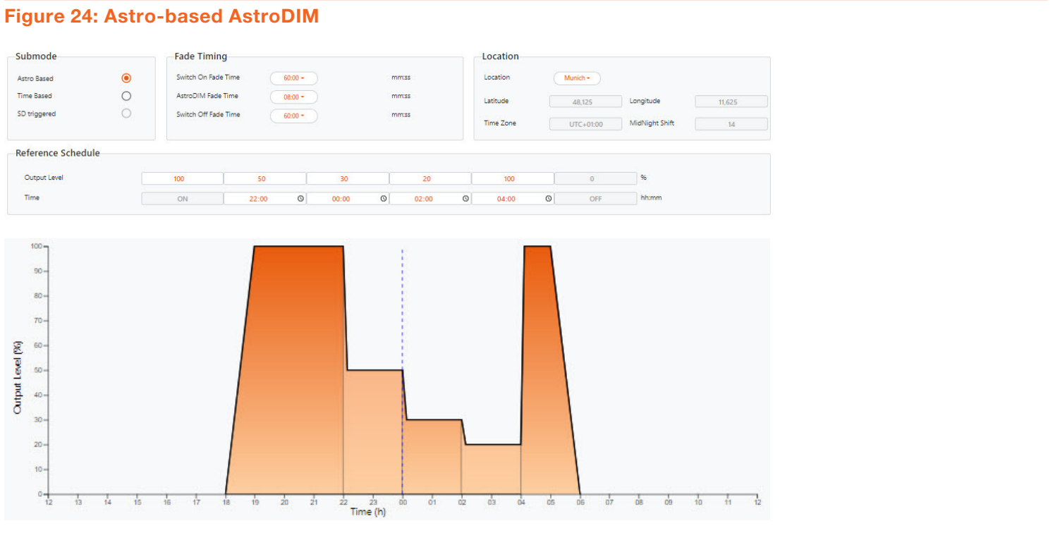
Fade timing: — AstroDIM fade time: Fade time between the different dimming levels. To achieve further energy savings in the twilight phase, the switch-on and switch-off fade time can be set to up to 60 minutes. — Switch-on fade time: Fade time after the LED driver has been powered on. The output level at the end of this fade time is defined by the output level of the related dimming period (step x). — Switch-off fade time: Fade time prior to the estimated power-off point. The switch-off fading is performed down to the minimum dimming current until the LED driver is switched off externally.
Table 7: Fade timing parameters (astro-based mode)
Parameter Min. Max. Default AstroDIM fade time 0, 2 s 8 min 3 min Switch-on fade time 0, 15 s 60 min 0 s Switch-off fade time OFF, 0 s 60 min OFF
five independent dimming periods can be defined in the reference schedule. The minimum length of one dimming period has to be longer than the AstroDIM fade time. Valid time values can be set between 12:00 pm and 11:59 am. If less than five output levels need to be performed, two sequenced levels have to be set to the same value.
The defined dimming profile is already performed after the second power-off/on cycle after programming.
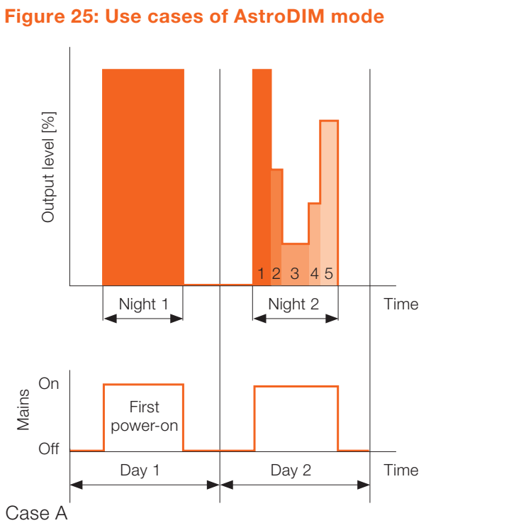
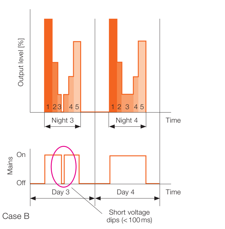
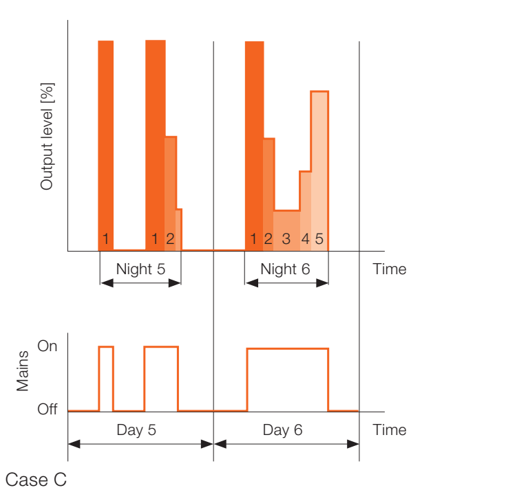
The AstroDIM profile is performed after the first valid on-time.
Voltage dips of less than 100 ms do not affect the on-time (case B).
If the on-time of the LED driver is shorter than 4 hours, it is not saved and therefore not used to calculate the next on-time (case C).
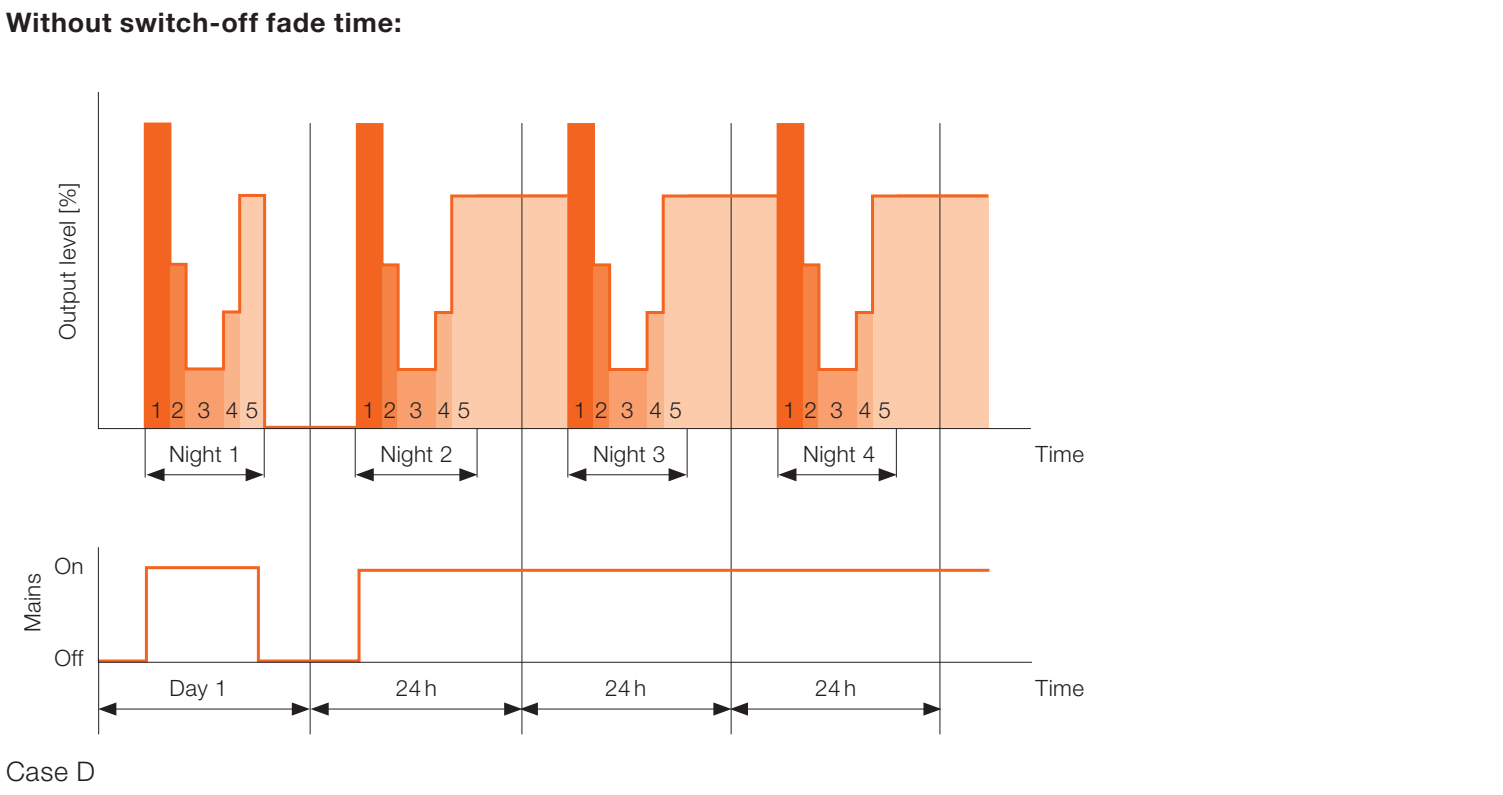
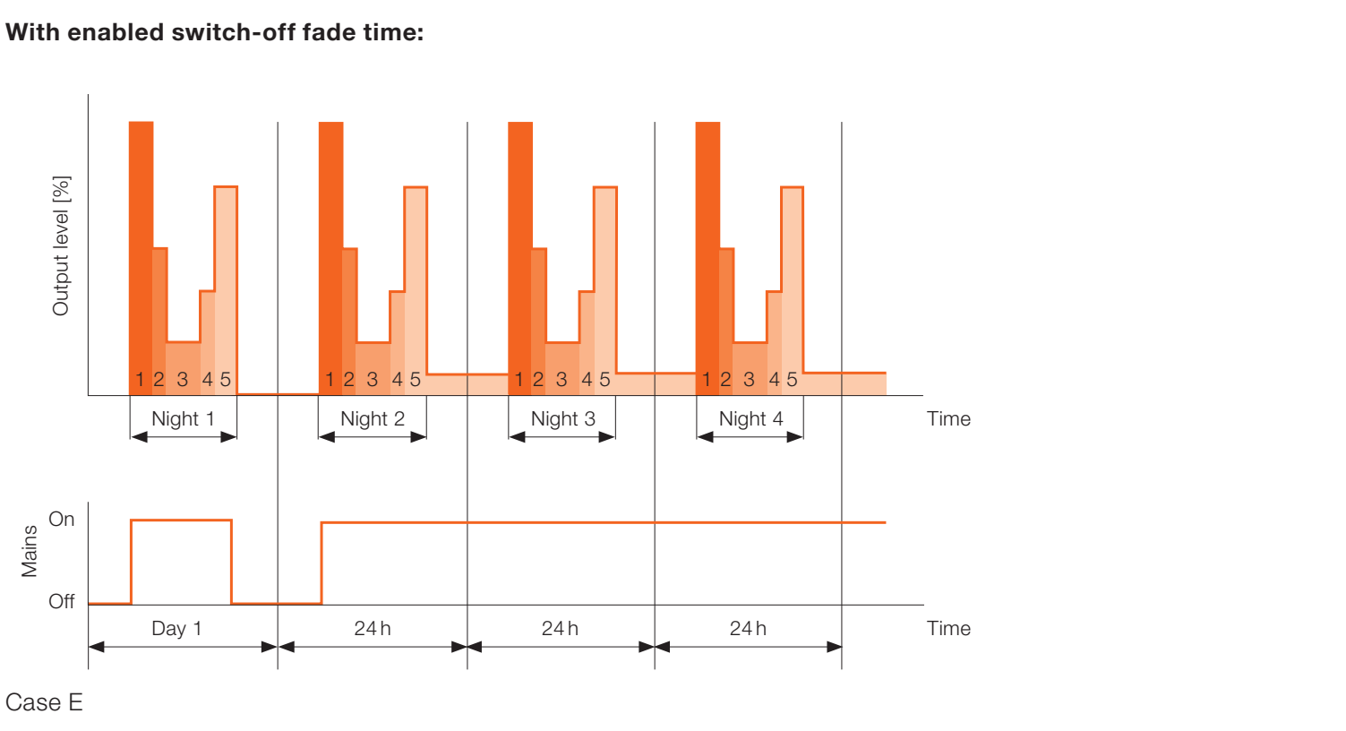
If the on-time of the LED driver is longer than 24 hours, it is not saved and therefore not used to calculate the next ontime.
Note:
If the 4DIM NFC G3 CE LED driver is operated longer than 24 hours, it cannot be assumed that the different dimming level will start at the same time, because the time base is affected by the accuracy of the mains frequency over the day, week, month and year.
3.2.4 Presence detection in AstroDIM mode
In the “AstroDIM PD (DALI)” dimming mode, it is possible to override the dimming profile of AstroDIM with the presence detection settings triggered by an external sensor (e.g. motion or presence sensor) that is connected to the SD(2) port. The sensor must support the electrical characteristics of the SD(2) port.
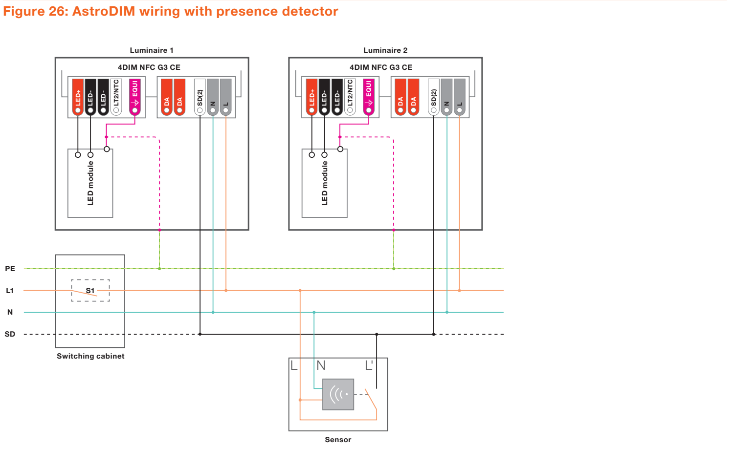
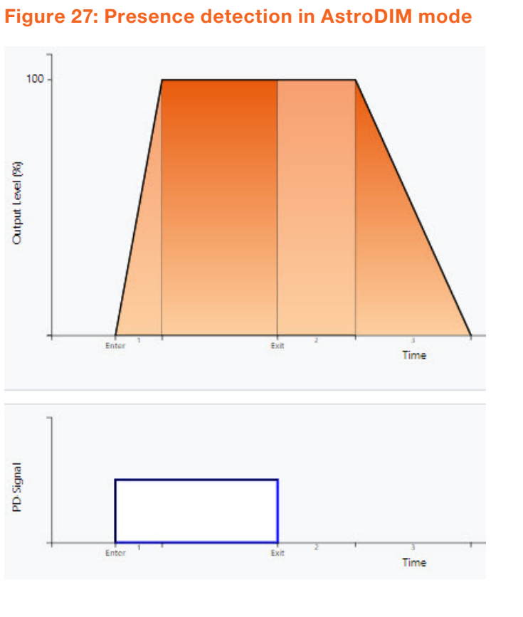
An active signal at the SD(2) port (PD signal) starts the presence detection profile, which is defined by the following four parameters:
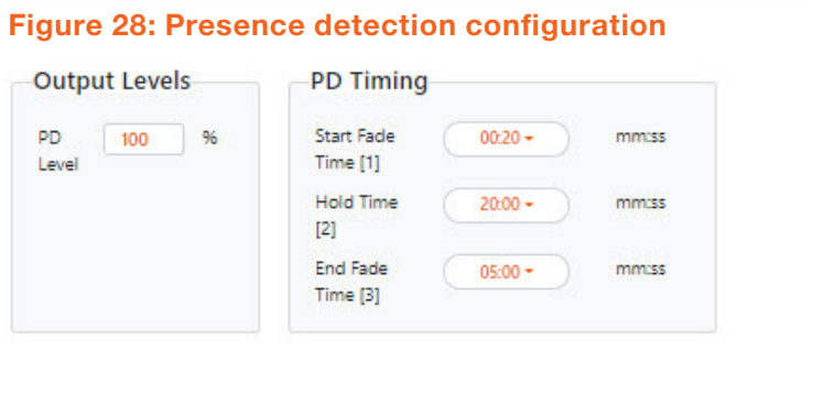
— PD level: Output level when the SD(2) port is active. — Start fade time: Fade time after the SD(2) port has become active. — Hold time: Hold time after the SD(2) port is not active anymore. — End fade time: Fade time after the hold period.
These parameters can be set using the Tuner4TRONIC® software, as shown in figure 28.
3.2.5 AstroDIM SD-triggered
In the “AstroDIM SD-triggered” dimming mode, it is possible to activate the dimming profile of AstroDIM with an active signal at the SD(2) port. Compared to the usual AstroDIM mode, where the dimming profile starts by switching on the LED driver, in the “AstroDIM SD-triggered” mode, the LED driver can be switched on and set to a defined output level until the trigger signal starts the dimming profile.
To activate this feature, select operating mode “AstroDIM + Presence Detection (DALI)” and, within the feature, choose the submode “SD-triggered”.
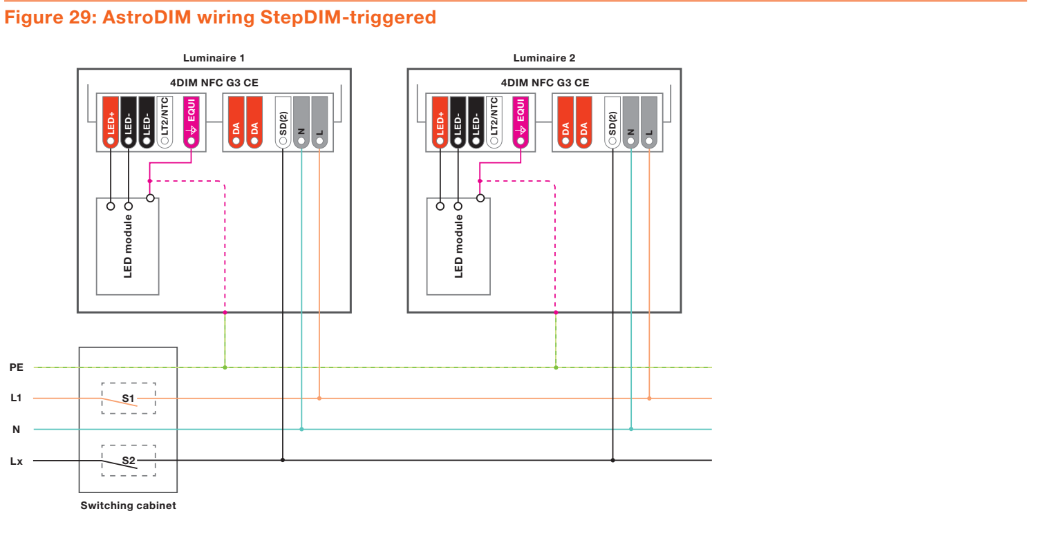
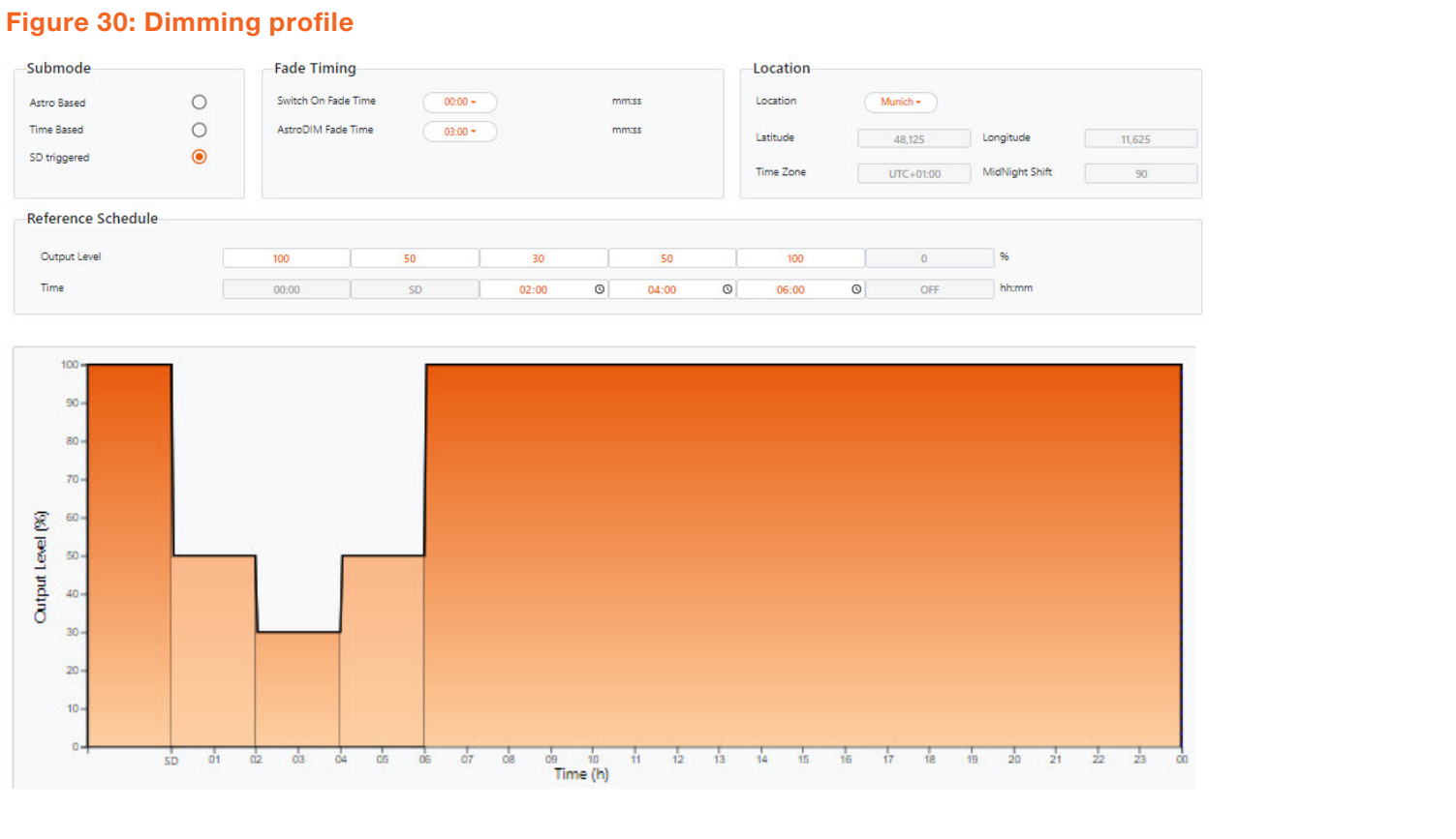
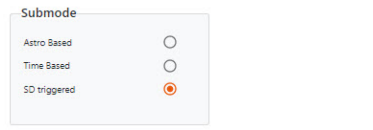
Figure 30 shows the dimming profile according to the reference schedule. The start of the dimming behavior is triggered by the SD signal and can be changed in the reference schedule table.
Table    8: Presence       detection      parameters
Parameter                    Min.              Max.             Default
PD  level                    OFF,  10 %        100 %            100  %
Start fade  time             0, 2 s            8 min            OFF
Hold  time                   0, 15 s           60 min           OFF
End  fade  time              0, 2 s            8 min            4 s
Warning:
If the output level falls below the minimum physical dimming level, the minimum physical dimming level is used by the LED driver. The software still displays the original value. If the output level falls below the minimum allowed dimming current, the value is visualized in red.
3.3 StepDIM feature
StepDIM is a one-step dimming mode using an additional control line or a switched phase (pilot line) to control one or more light points and set the light output to a preprogrammed light level. The SD level and the fade time can be set using the Tuner4TRONIC® software.
There are three different StepDIM operating modes: — StepDIM (DALI) — StepDIM inverse (DALI) — StepDIM inverse, autodetect (DALI)
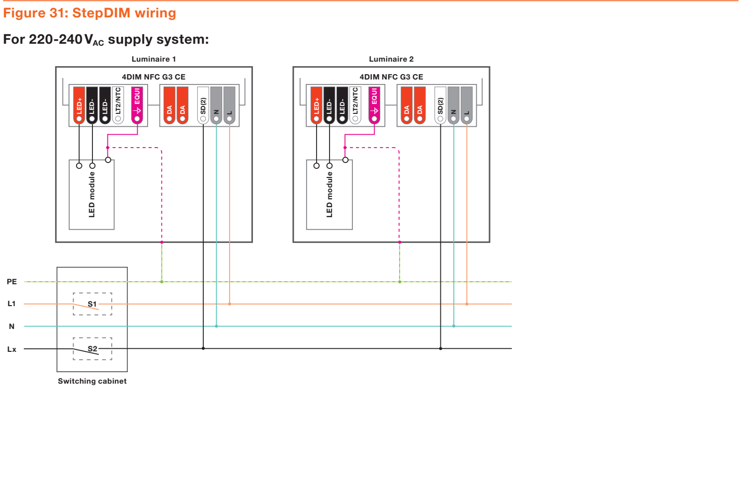
For StepDIM operation, the LED driver is connected to the mains and a control line or a switched phase. Figure 31 shows the connection for the two different supply voltage systems.
The StepDIM application is supported by the following supply systems:
SD port SD(2) supports both single-phase and three-phase supply systems with a nominal voltage of 220-240 V , AC 50/60 Hz.
The StepDIM port (SD(2)) of the 4DIM NFC G3 CE LED driver is triggered by an input current referenced to the neutral (N) and, if the signal is stable for more than 500 ms, the SD(2) port fulfills the following electrical characteristics:
Table    9: Electrical     characteristics         of  the   StepDIM
port   (SD(2))
StepDIM    signal          Input  current             Input  voltage
                           SD(2)  port                SD(2)  port  (SD(2)-N)
Active (high)              > 2.0 mA                   or > 196 V
Active (high) > 2.0 mA or > 196 V peak AC Inactive (low) < 0.5 mA – peak
In some installations, leakage currents might occur between the different phases due to old or damaged cables, which have insufficient insulation or high-capacitance coupling. The unit can be triggered if the leakage currents exceed the inactive SD(2) input current. False triggering can be avoided by connecting the SD(2) input to the neutral or using a bypass capacitance/resistance between SD(2) and N.
3.3.1 StepDIM
If, in the “StepDIM (DALI)” mode, the switch (S2) is closed and the phase voltage Lx is applied to the SD(2) port (SD active), the output level is set to the SD(2) level. Leaving the SD(2) port floating (SD inactive), the output level is set to the nominal level.
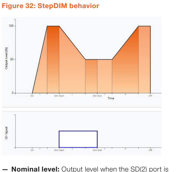
not active. — SD level: Output level when the SD(2) port is active. — Switch-on fade time: Fade time after power-on. — Start fade time: Fade time after the SD(2) port has become active. — Hold time: Hold time after the SD(2) port is not active anymore. — End fade time: Fade time after the hold period.
These parameters can be set using the Tuner4TRONIC® software, as shown in figure 33.
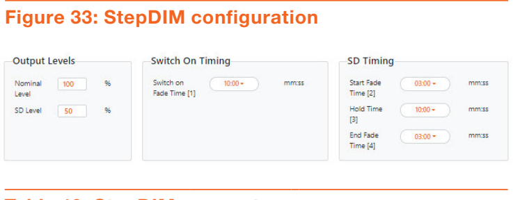
Table    10:  StepDIM       parameters
Parameter                    Min.              Max.             Default
Nominal   level              OFF,  10 %        100 %            100  %
SD  level                    OFF,  10 %        100 %            50 %
Switch-on   fade  time       0, 15 s           60 min           0 s
Start fade  time             0, 2 s            8 min            3 min
Hold  time                   0, 15 s           60 min           OFF
End  fade  time              0, 2 s            8 min            3 min
End fade time 0, 2 s 8 min 3 min
Warning:
If the output level falls below the minimum physical dimming level, the minimum physical dimming level is used by the LED driver. The software still displays the original value. If the output level falls below the minimum allowed dimming current, the value is visualized in red.
3.3.2 StepDIM inverse
For the “StepDIM inverse (DALI)” mode, the behavior is inverted. If the switch (S2) is opened and the SD(2) port is floating (SD inactive), the output level is set to the SD level. If a phase voltage is applied to the SD(2) port (SD active), the output level is set to the nominal level.
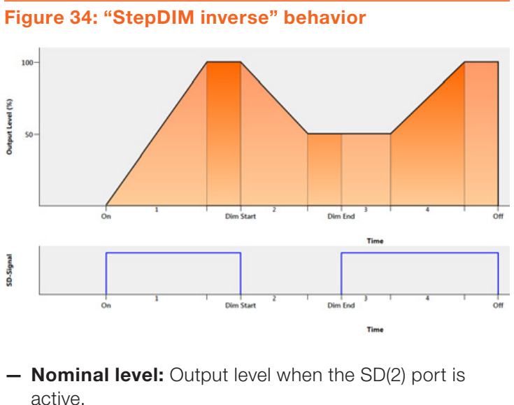
— SD level: Output level when the SD(2) port is not active. — Switch-on fade time: Fade time after power-on. — Start fade time: Fade time after the SD(2) port is not active anymore. — Hold time: Hold time after the SD(2) port has become active. — End fade time: Fade time after the hold period.
3.3.3 Autodetect, ON/OFF-StepDIM inverse
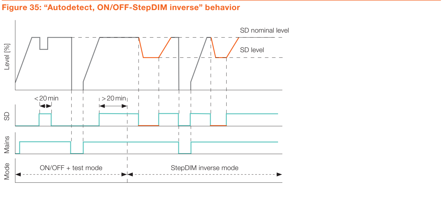
In the “Autodetect, ON/OFF-StepDIM inverse (DALI)” mode, the LED driver automatically detects if it is used in a simple on/off environment or in a StepDIM inverse installation. If a valid “high” signal (SD active) is detected at the SD(2) port for longer than 20 minutes, the LED driver automatically switches to the “StepDIM inverse” mode. In order to be able to test the correct wiring of the luminaire during the production phase, the first “high” signal at the SD terminal will reduce the light output level to the StepDIM dimming level without changing the driver to the “StepDIM inverse” o perating mode.
This feature allows minimizing the number of different luminaire configurations and keeps the stock lean.
Example: In some parts of StepDIM installations (e.g. roundabouts or pedestrian crossings), the light output of the installed fixtures should not be reduced during the night. With the “autodetect” feature, all LED drivers can be programmed with the same settings: While the on/off fixtures (SD(2) port not connected) still provide the full light output, the others perform the requested dimming profile.
3.3.4 Autodetect, AstroDIM-StepDIM inverse
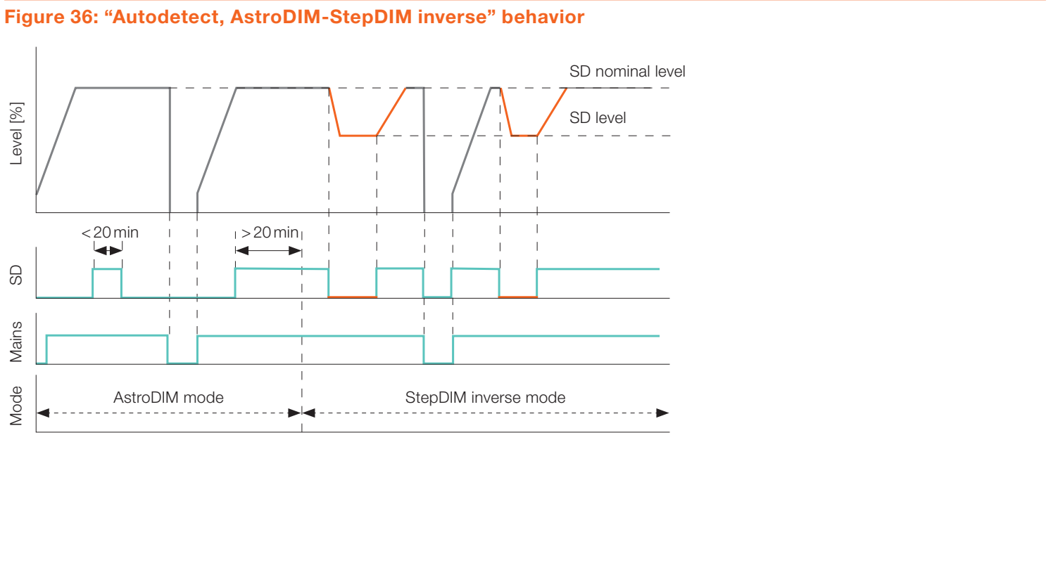
In the “Autodetect, AstroDIM-StepDIM inverse (DALI)” mode, the LED driver automatically detects if it is used in an AstroDIM environment or in a StepDIM inverse installation. If a valid “high” signal (SD active) is detected at the SD(2) port for longer than 20 minutes, the LED driver automatically switches to the “StepDIM inverse” mode.
Example: The most common usage in outdoor applications is either StepDIM or AstroDIM. With the “Autodetect AstroDIMStepDIM inverse” mode, all LED drivers can be programmed with the same settings: While the AstroDIM fixtures (SD(2) port not connected) still provide the individual AstroDIM profile, the others perform the requested dimming behavior via StepDIM.
3.4 MainsDIM feature
The reduction of the mains amplitude is partly used for the dimming of conventional lamps. In the MainsDIM operating mode, the output current of the LED driver depends on the mains input voltage. Standard electronic drivers compensate for fluctuations in the input voltage and do not support this function. No additional control wires are needed in this dimming mode (see figure 37).
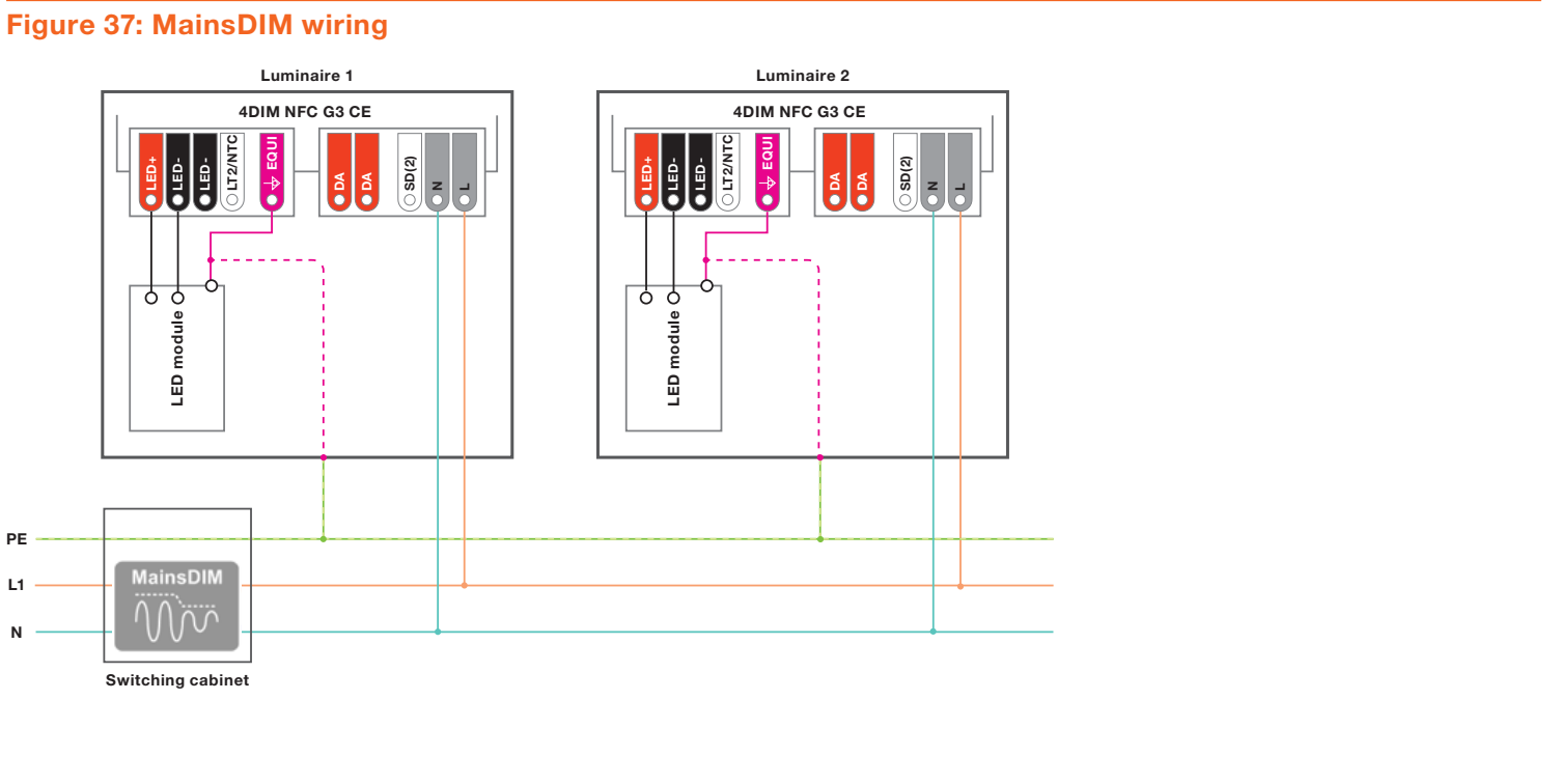
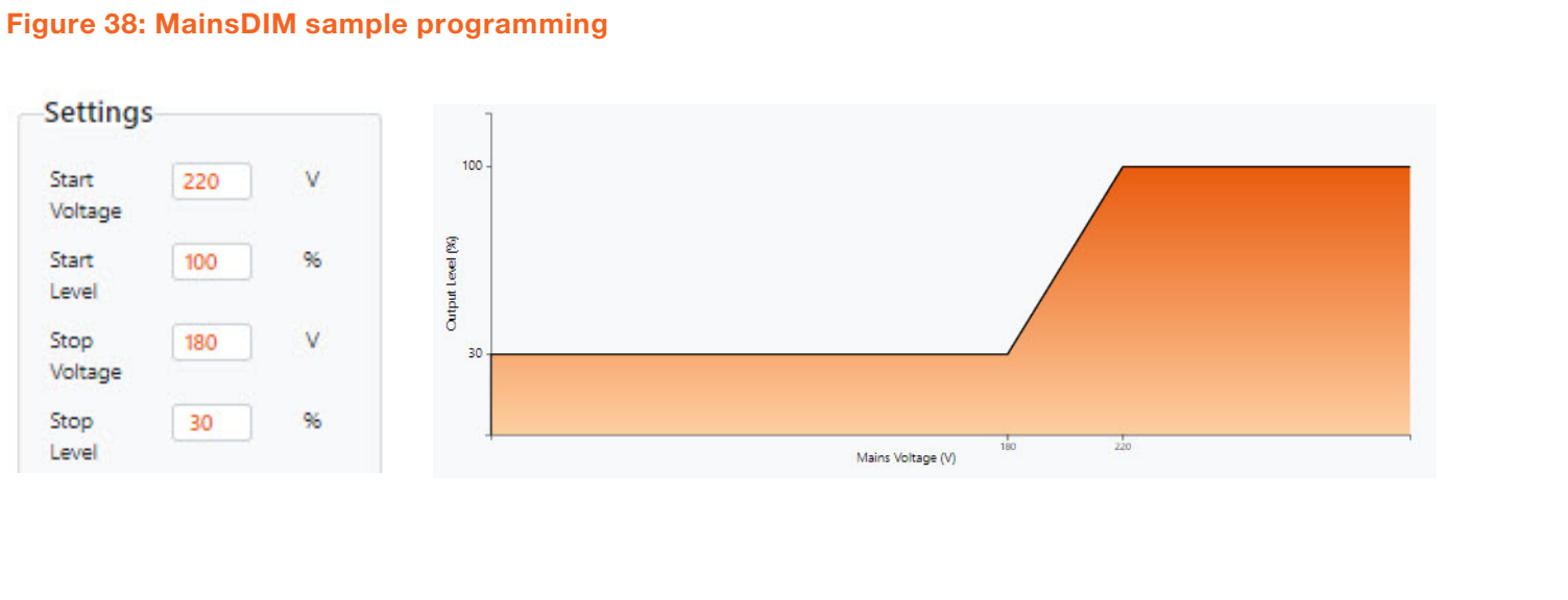
The dimming behavior of the LED driver can be programmed using the Tuner4TRONIC® software. The programmable values can be found in table 11.
Table 11: MainsDIM parameters
Parameter               Min.          Max.           Increment     Default
Start voltage           190  V        250  V         1 V           220 V
Start level             30 %          100  %         1 %           100 %
Stop  voltage           170  V        230  V         1 V           180 V
Stop  level             10 %          85 %           1 %           30 %
Start-stop  voltage     20 V          -              -             -
Warning:
If the output    level  falls below    the  minimum      physical    dim-
ming   level,  the  minimum      physical    dimming     level  is used    by
ming level, the minimum physical dimming level is used by the LED driver. The software still displays the original value. If the output level falls below the minimum allowed dimming current, the value is visualized in red.
Note:
To increase the light output stability against small voltage fluctuations, a minimum voltage difference of 5 V from the “start voltage” is necessary to trigger the dimming of the LED driver. The triggering of the dimming is performed with a delay time of approximately 1 to 2 seconds. The setting of the thresholds should also consider the voltage drop in the real installation due to cable and contact resistance.
3.5 DALI operating mode
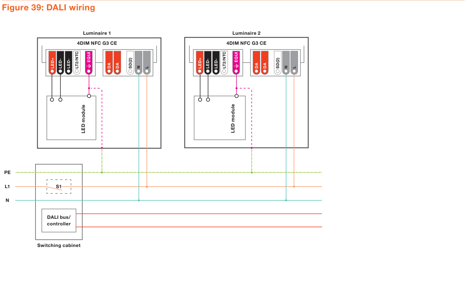
For DALI operation, the 4DIM NFC G3 CE LED driver is connected to the mains and to a DALI controller or DALI bus (see figure 39). The additional DALI wires can be installed alongside the mains wires.
3.6 DC operation feature
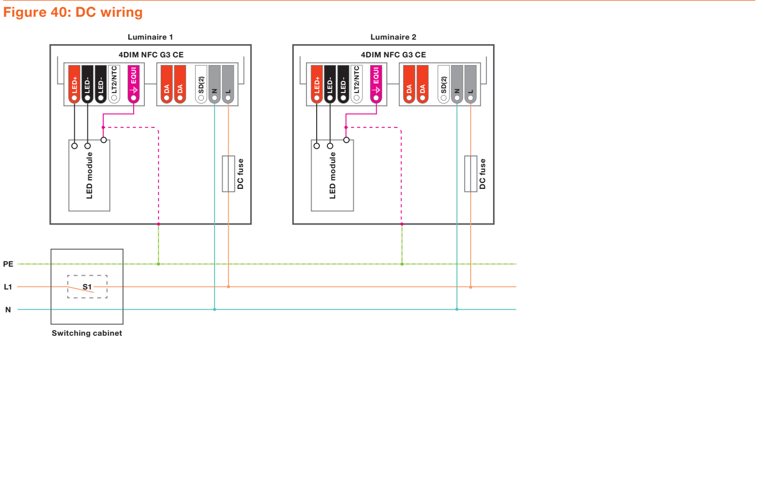
4DIM NFC G3 CE LED drivers are prepared for a DC grid operation. As the built-in 4DIM NFC G3 CE LED driver fuse is not rated for DC operation, an external rated DC fuse has to be installed in front of the driver. The output current in DC operation can be set via the Tuner4TRONIC® software.
Most Inventronics LED drivers are compatible with emergency components from leading emergency lighting companies.
For detailed information on DC operation of our drivers and certificates of compatible components, please consider our “Application notes for DC operation”, which can be found in our OEM Download Center via the following link: https://www.inventronics-light.com/application-guides
4 Additional information
4.1 Insulation
4DIM NFC G3 CE LED drivers have a double/reinforced insulation between the primary and the secondary side and a double/reinforced insulation between all electronic parts and the casing.
Table 12: Insulation and U
out
-071/02
TO
MID4
0A1/042
EC
3G
CFN
-071/04
TO
MID4
7A0/042
EC
3G
CFN
-071/04
TO
MID4
0A1/042
EC
3G
CFN
-071/57
TO
MID4
7A0/042
EC
3G
CFN
-071/57
TO
MID4
0A1/042
EC
3G
CFN
-071/57
TO
MID4
5A1/042
EC
3G
CFN
-071/011
TO
MID4
7A0/042
EC
3G
CFN
-071/011
TO
MID4
0A1/042
EC
3G
CFN
-071/561
TO
MID4
0A1/042
EC
3G
CFN
-071/002
TO
MID4
0A1/042
EC
3G
CFN
Insulation
(primary/secondary)
SELV SELV SELV Double SELV SELV Double Double Double Double
Insulation of casing
Double Double Double Double Double Double Double Double Double Double
U 60 V 120 V 60 V 185 V 120 V 120 V 250 V 220 V 320 V 370 V
out
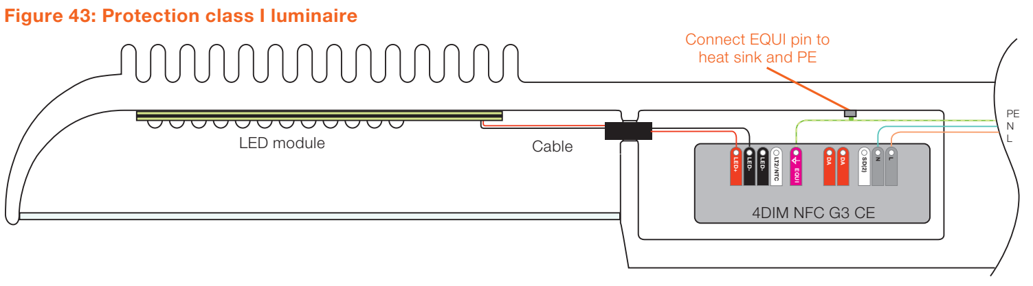
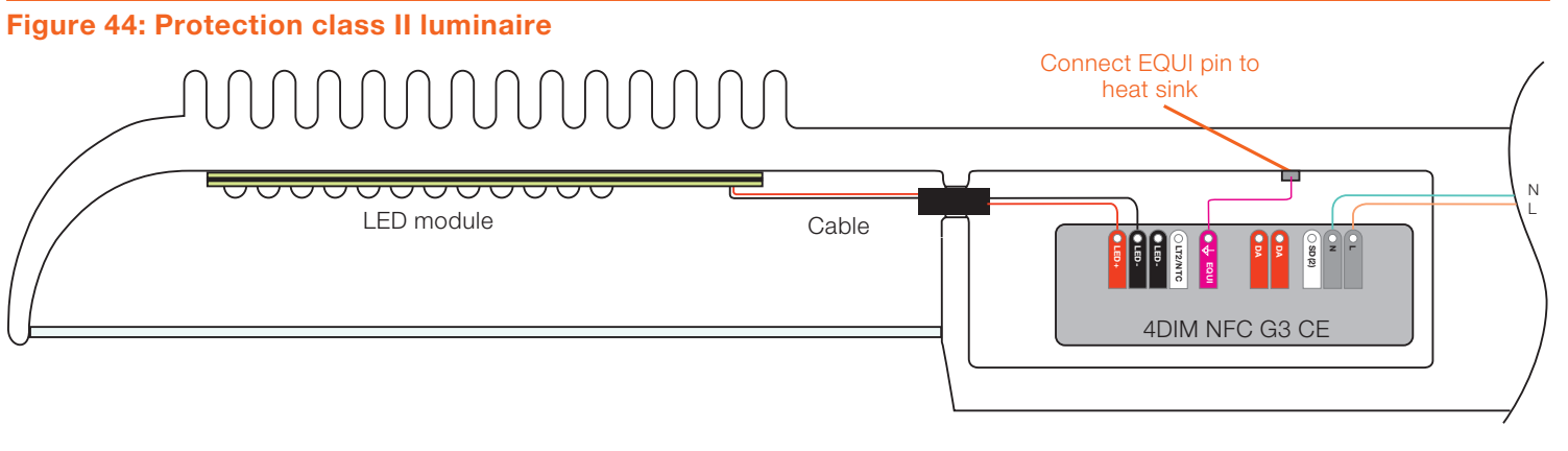
The equipotential pin (EQUI) meets the requirements for double insulation versus the primary side and requirements for basic insulation versus the secondary side (it complies with the requirements of IEC 60598-1 Annex A – “safe to be touched” – in case of insulation fault between all secondary circuits and accessible conductive parts).
The detailed insulation levels are defined in the instruction sheet of the product.
4.2 Cable preparation
4DIM NFC G3 CE LED drivers use open terminals for easy and quick wiring. To ensure a safe and stable hold of the wires,
4DIM NFC G3 CE LED drivers use open terminals for easy an the insulation of the cables should be stripped accordingly. S
Primary side:
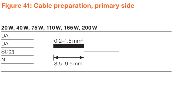
d quick wiring. To ensure a safe and stable hold of the wires, olid and flexible wires can be used.
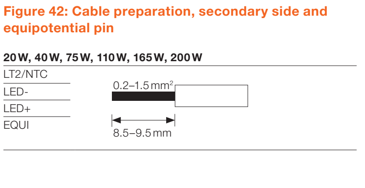
4.3 Incorrect wiring on the output side
4DIM NFC G3 CE LED drivers are inherently protected against incorrect wiring on the output side. Incorrect wiring between LED+ and LEDset or NTCset can irreversibly damage the LED driver. If there is a short circuit between LED+ and LED-, the LED driver shuts down and tries to switch the load back on. The same behavior might occur if the output voltage falls below the minimum allowed voltage.
4.4 Input overvoltage
The driver withstands an input voltage of up to 305 V for AC an unlimited time, but a shutdown of the output load might occur in case the supply voltage exceeds 270 V . In case AC of miswiring, the driver can withstand up to 360 V for no AC longer than two hours. Under operation conditions in which overvoltage levels >264 V occur, the product needs to be AC additionally protected by an external fuse (400 V, 4 A, time lag, I2 t > 160 A2 sec).
Table 13: 4DIM NFC G3 CE surge protection levels
4.5 Surge protection
4DIM NFC G3 CE LED drivers offer a common-mode protection level of up to 10 kV with an integrated overvoltage suppression for the connected LED module, which minimizes the stress on the LED module and thus ensures high reliability in the field. To achieve the surge protection levels, the EQUI pin needs to be connected to the heat sink of the LED module (see figures 43 and 44). The EQUI pin meets the insulation requirements for protection class I and II luminaires. The protection level between L and N or SD(2) and N is 6 kV.
In addition, the SD port contains an active surge suppression element referenced to N. In case an external surge protection device (SPD) is used to protect the DALI port and the mains input, the protection level U of the SPD P between DALI port to earth and mains input to earth should be equal. Connecting only an external SPD to the DALI port with a connection to earth is not allowed.
The following protection levels can be achieved for class I and II luminaires:
Surge   between                        Test  description                         Product    standard                       Basic   standard
L-N/SD-L/SD-N                          6 kV  at 2 Ω, differential mode           IEC/EN   61547                            IEC  61000-4-5
DA+  - DA-                             1 kV  at 2 Ω, differential mode           –                                         IEC  61000-4-5
L-EQUI/N-EQUI/SD-EQUI                  10 kV  at 12 Ω,  common    mode           IEC/EN   61547                            IEC  61000-4-5
(DA+/DA-)   - PE                       8 kV  at 12 Ω, common     mode            IEC/EN   61547                            IEC  61000-4-5
L-DA/N-DA/SD-DA                        6 kV  at 12 Ω, common     mode            IEC/EN   61547                            IEC  61000-4-5
If an additional external surge protection device is used, please contact your Inventronics sales contact for support.
5 Programming
4DIM NFC G3 CE LED drivers can be programmed using Tuner4TRONIC® either via DALI or NFC. Please find details on the Tuner4TRONIC® tool chain, user manuals, application guides, tutorials and download links on https://www.inventronics-light.com/tuner4tronic
Note:
Performance check: If electronically controlled control gears are combined with electrical power supplies, the electronic circuits of both devices might influence each other. This could lead to wrong measurements (e.g. lower power factor).
5.1 Programming with DALI magic
4DIM NFC G3 CE LED drivers need to be powered during programming with DALI magic.
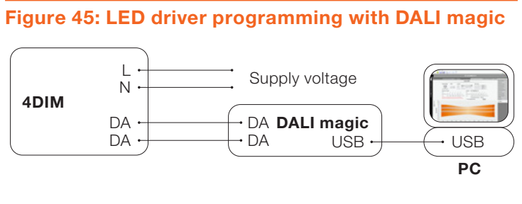
Table    14:  Supply     voltage     during     programming
Supply                     Power                      Ambient
voltage                                               temperature
220–240   V                All types                  Acc.  to LED
           AC
                                                      driver datasheet
5.2 Programming with NFC USB readers
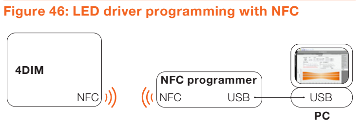
4DIM NFC G3 CE LED drivers must not be powered during programming with T4T-Production via NFC. Place the LED driver on the NFC reader and align the antennas of both devices. The position of the NFC antenna is indicated by the NFC logo on the label of the LED driver and is mounted vertically at the side of the driver’s housing. When using box programming, the NFC logo on the box needs to be placed in the center of the FEIG Antenna ANT310/310. Please find a list of supported NFC readers in the T4TProduction user manual.
Please note:
The NFC antenna of the 4DIM NFC G3 CE has been optimized for an easy accessibility from the top surface of the LED driver. This enables an optimal access to NFC tags also in very narrow luminaires, in which very often not enough space is left between the luminaire and the LED driver's side surface. This eases the service operation in the field via the T4T Field App. For single LED driver programming during production, ensure that the antenna is placed on the top surface of the LED driver.
Note:
A power-off/on cycle is necessary to activate the password settings in ConfigLock.
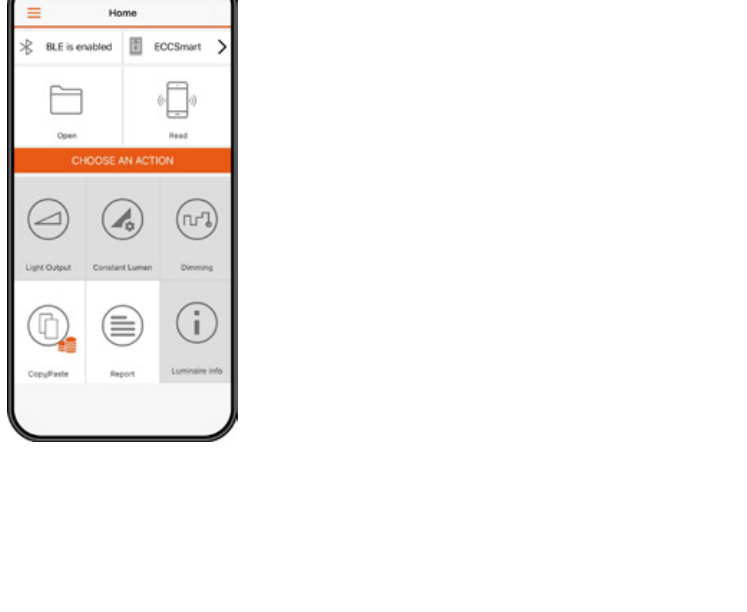
5.3 Programming with T4T-Field App
4DIM NFC G3 CE LED drivers can be programmed via NFC with the Tuner4TRONIC® Field App available for download to Android and iOS mobile devices from GooglePlay and AppStore. The T4T-Field App allows reading driver data, programming drivers from production files and editing data such as light output, CLO, dimming profiles and luminaire info data. Reading and writing data with the T4T-Field App is possible with and without powering the driver with mains. Programming data may be restricted by password settings from the luminaire manufacturer.
6 Additional information for electrical design-in
6.1 Recommended EMI wiring setup
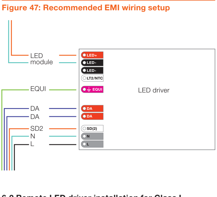
In order to fullfill EMI requirements, the following precautions need to be taken into account: — Keep LED output wires close together and avoid loop areas. — Keep the wiring length as short as possible. — Keep the length of the mains wires as short as possible. — Keep mains and control wires separated from the LED output wires. — Avoid any wiring over the driver housing.
A recommended wiring setup is shown in figure 47.
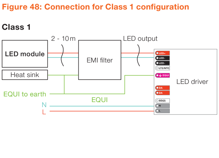
6.2 Remote LED driver installation for Class I configuration
Remote mounting of LED drivers is allowed as long as the additional voltage drop on the output wires is accounted for.
For Class I configurations, in case of remote driver installation (output wires with a length between 2 and 10 meters), an EMI filter, as shown in Figure 48, can be used in order to comply with the EMI requirements.
6.3 Remote LED driver installation for Class II configuration
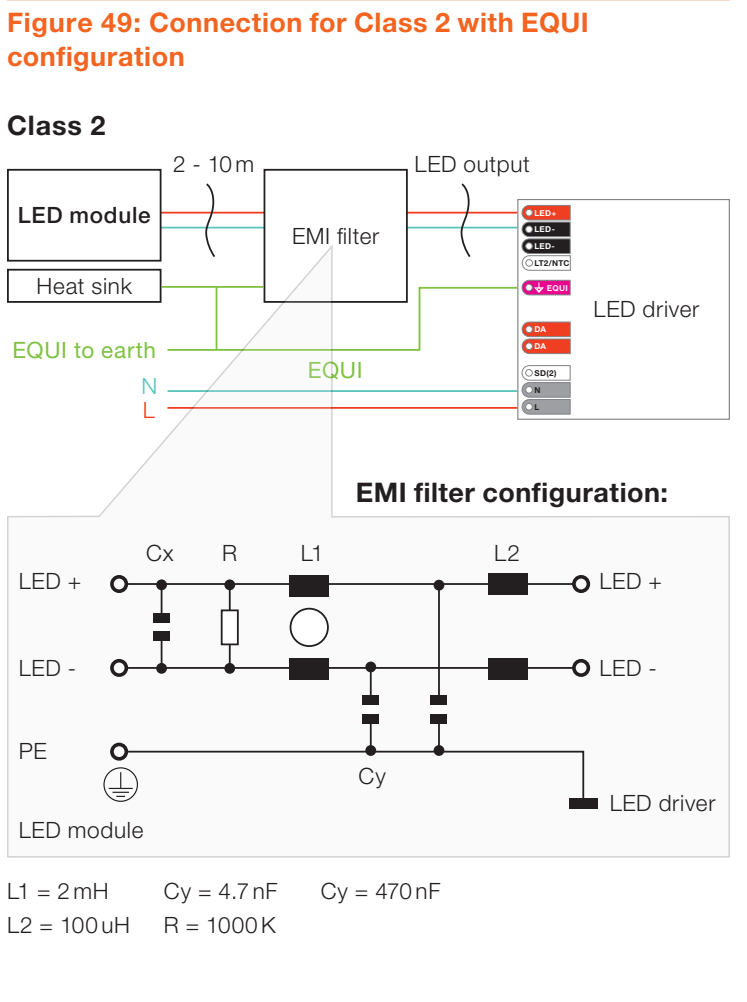
Remote mounting of LED drivers is allowed as long as the additional voltage drop on the output wires is accounted for.
For Class II configurations, in case of remote driver installation (output wires with a length between 2 and 10 meters), an EMI filter, as shown in figure 49, can be used in order to comply with the EMI requirements.
Disclaimer
All information contained in this document has been collected, analyzed and verified with great care by Inventronics. However, Inventronics is not responsible for the correctness and completeness of the information contained in this document and Inventronics cannot be made liable for any damage that occurs in connection with the use of and/or reliance on the content of this document. The information contained in this document reflects the current state of knowledge on the date of issue.
Service contact
Inventronics GmbH · Parkring 31-33, 85748 Garching, Germany
Inventronics · support@inventronicsglobal.com · Contact form