
Tuner4TRONIC Configurator (T4T-C) - User Manual
Create LED driver configurations online, set operating and dimming features, manage Configuration Lock, and download Production Files for programming.
Updated · by Administrator
On this page
- Please note
- 1 Tuner4TRONIC Toolset
- 2 General
- 3 Using T4T Configurator
- 3.1 Start Page
- 3.2 Select Device Page
- 3.3 Driver Page
- 3.3.1 Operating Mode
- 3.3.2 Feature Tabs
- 3.3.3 Operating Current
- 3.3.4 Tuning Factor
- 3.3.5 Soft Switch Off
- 3.3.6 Dim to Dark
- 3.3.7 Dimming below 1%
- 3.3.8 Dimming below 10%
- 3.3.9 Configuration Lock
- 3.3.10 Driver Guard
- 3.3.11 Permanent Shutdown
- 3.3.12 End of Life
- 3.3.13 Lamp Operating Time
- 3.3.14 DALI/DEXAL Settings
- 3.3.15 DALI Addressing
- 3.3.16 0-10V Settings
- 3.3.17 Thermal Protection
- 3.3.18 Constant Lumen Output (CLO)
- 3.3.19 MainsDIM
- 3.3.20 StepDIM
- 3.3.21 AstroDIM
- 3.3.22 Emergency Mode
- 3.3.23 Corridor Functionality
- 3.3.24 TouchDIM + Sensor
- 3.3.25 LED Module Operating Data
- 3.3.26 Channel Error Control
- 3.3.27 Dimming
- 3.3.28 Power-On Delay
- 3.3.29 Smart SPD Monitoring
- 3.3.30 PWM Dim Mode
- 3.3.31 Repeater Settings
- 3.4 Multiple Drivers
- 3.5 Summary Page
- 3.6 Download
- Service contact
Tuner4TRONIC Configurator (T4T-C) - User Manual
This manual is based on the August 2024 T4T Configurator user manual.
Please note
All information in this guide has been prepared with great care. Inventronics, however, does not accept liability for possible errors, changes and/or omissions. Please check www.inventronicsglobal.com or contact your sales partner for an updated copy of this guide.
This technical application guide is for information purposes only and aims to support you in tackling the challenges and taking full advantage of all opportunities the technology has to offer. It is based on Inventronics' own measurements, tests, specific parameters and assumptions. Individual applications may not be covered and may need different handling. Responsibility and testing obligations remain with the luminaire manufacturer/OEM/application planner.
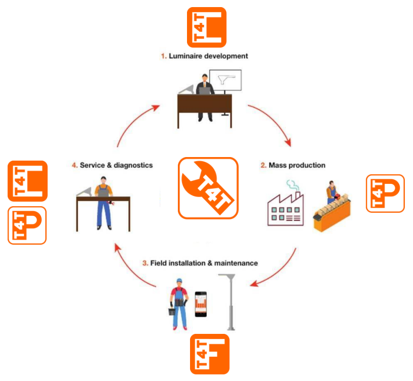
1 Tuner4TRONIC Toolset
The Tuner4TRONIC (T4T) software suite allows luminaire manufacturers to program Inventronics drivers via DALI and/or NFC in a simple, fast, reliable, and cost-effective way, speeding up the production process. Tuner4TRONIC tools can be downloaded from Inventronics Tuner4TRONIC downloads
2 General
Tuner4TRONIC Configurator allows users to enter data required to configure Inventronics LED drivers.
The output of T4T Configurator is an encrypted production file (.osrtup) that can be transferred to Tuner4TRONIC Production (T4T-P) to program Inventronics LED drivers. Tuner4TRONIC Configurator also allows importing data read back from drivers or production or luminaire files to visualize and use as templates for new production files.
The Tuner4TRONIC Configurator is a browser-based application, processing data in the cloud. No installation is required to run Tuner4TRONIC Configurator - simply open Tuner4TRONIC Configurator in your Google Chrome or Mozilla Firefox browser.
No access key is required to access the Tuner4TRONIC Configurator in public mode. There is no restriction in public mode with respect to functionality; therefore, Tuner4TRONIC Configurator can be used productively without limitations.
Important: Projects created in public mode are visible to all users and can be edited and deleted by all users. This includes password settings in ConfigLock in the driver data.
Projects will be deleted in public mode by default when creating a production file to avoid data leaks. In order to allow saving projects in a private workspace, an Inventronics customer may apply for a free access key at T4Tsupport@inventronicsglobal.com (one access key per Inventronics customer ID) to grant access to a private workspace in the cloud that is not visible to any other users.
A standard workflow includes:
- Create or open a project from the cloud, create one from scratch and select drivers, or import a file from your computer.
- Edit the configuration data.
- Finish and download a Production File (
.osrtup).
Supported import files:
| File | Source |
|---|---|
.osrtup |
Production File. |
.osrtur |
Raw driver readback data created by T4T Production or the T4T Field app. |
.osrtul |
Luminaire file created with T4T Development. |
Validation rules immediately identify data outside limits or settings that conflict with related parameters.
3 Using T4T Configurator
3.1 Start Page
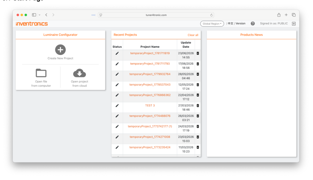
To start T4T Configurator enter Tuner4TRONIC website in the browser and press the start button in the line T4T Configurator. A project can be created from scratch, by opening files from the local computer or by opening existing projects from the cloud. Recent projects can be picked from the list of recent projects.
Deleting projects in the recent projects list will remove projects from the recent projects list only. To remove projects in the cloud, select open project from cloud and press the delete icon on that page. The user can return to the start page at any time by clicking on the Inventronics logo (top left on each page).
3.2 Select Device Page
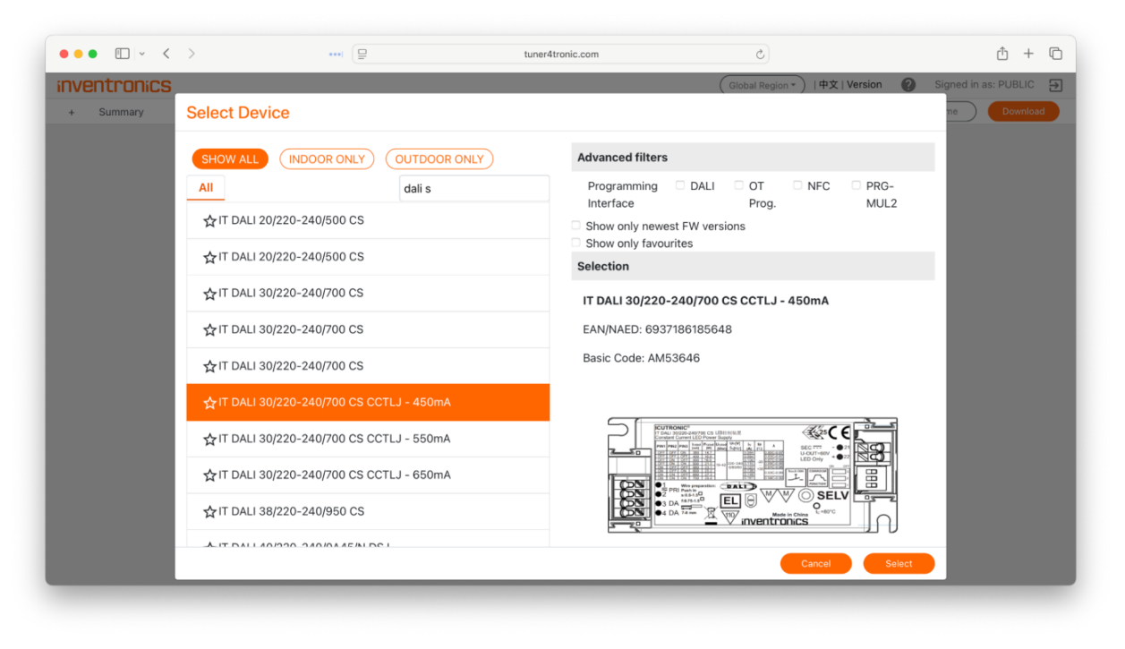
The select device page will open by default if a project is created from scratch or no driver has been assigned to the project. The device (LED driver) can be selected by entering parts of the driver name or IC or EAN in the search field and filter settings. Ticking “Show only newest FW versions” will show the latest driver versions only.
Ticking “Show only favourites” will show favourites selected by toggling the star icon next to the driver. A picture and some driver data will help the user to identify the correct selection. Press the select button or double-click the line to confirm selection. To exit without selecting a driver press Cancel or ESC.
3.3 Driver Page
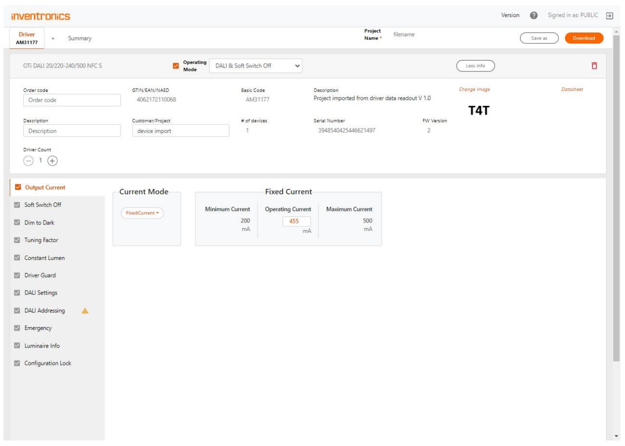
Press the driver tab in the top line to open the driver page. The driver page allows users to enter all data required by the driver, including project-related data. When opening a project from scratch and selecting a driver, data is filled with default settings provided by the device description file from the DD store in the cloud. The default project name can be changed at any time by pressing change project name. Press “More info” to read and edit driver and luminaire related data.
Click on the feature tabs in the left column to open the editable data fields. The number of feature tabs depends on the features supported by the driver and the operating mode selected in the header.
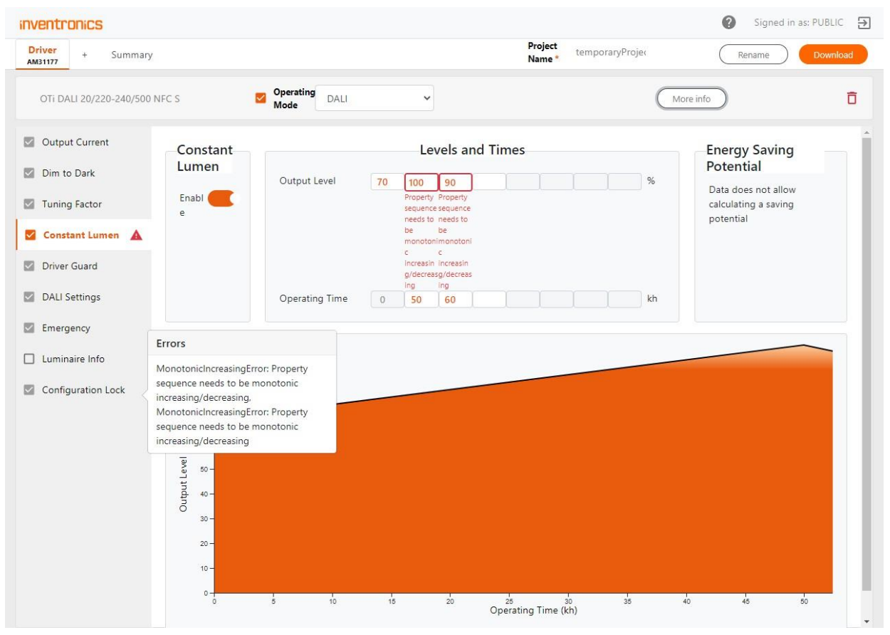
Data violating validation rules will be highlighted by an alert icon. Clicking the alert icon will provide details on violations.
Press “More info” to access additional information on the driver, e.g. GTIN and BaseCode (first 7 digits from IC on the driver label), Serial Number (only available when reading data from LED drivers), FW version, luminaire image and driver datasheet. Select Driver Count > 1, to enable multiple driver programming via DALI.
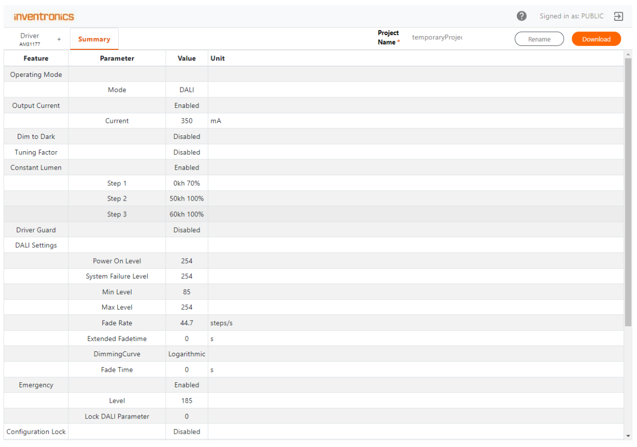
Press “Summary” tab in the header to display all settings in a table.
Once all data is final, press “Download” to create and download a production file. The name of the production file matches the name of the project. To change the project name, press the “Rename” button.
The production file will be copied to your local download folder. In public mode, the project will be deleted after having created a production file.
The production file is encrypted to hide the passwords entered in Configuration Lock. When opening a production file with Tuner4TRONIC Production, the passwords will be programmed but never displayed.
When reading a production file or a readback file (raw data from readout drivers) with Tuner4TRONIC Configurator, passwords will be stripped off. If the user wants to create a new production file based on an imported production file or readback file, the user needs to enter the password manually.
3.3.1 Operating Mode
First select the operating mode, e.g. TouchDIM (indoor drivers) or AstroDIM (outdoor drivers). There are standard modes (e.g. DALI DT8) and Inventronics proprietary modes. The dropdown list shows the operating modes available with the selected driver.
3.3.2 Feature Tabs
Each LED driver has its own feature set. The number of feature tabs on the left side of the page may also depend on the selected operating mode. The checkbox next to the feature tab indicates whether the settings in the feature tab will be programmed (skipped if not checked). Only data in features that are checked will be programmed. Data in the driver for unchecked features will not be overwritten. Partial programming helps reduce programming time with DALI and allows creating production files for programming with restricted permissions (see the Programming Options page: Programming as service).
3.3.3 Operating Current
This feature is used to adjust the output current of the LED driver. Different options of setting the current are available according to the LED driver interface type. LEDset is a multi-vendor LED module interface which allows users to set the operating current for the LED module by using a resistor.
Compared to setting the current by using the LEDset interface, a higher current resolution can be achieved by selecting the FixedCurrent mode through programming with Tuner4TRONIC (no resistor needed). In this mode the LEDset2 interface is disabled. In FixedCurrent Mode the operating current can be set within the limits given by min and max current. Entering values that exceed the limits will be indicated as an error. No production file can be created with errors.
3.3.4 Tuning Factor
Output current setting can be adjusted by the tuning factor, if supported by the driver. Tuning Factor can be used to fine-tune the light output for modules with a predefined lumen package.
Adjusted output current [mA] = Output Current [mA] × Tuning Factor [%] / 100
Tuning Factor can be set by Tuner4TRONIC Field app in the installation. A reference lumen value (valid for 100% of the tuning level) can be set to allow Tuner4TRONIC Field app to display the actual lumen output.
T4T Field app will display output current in mA and % only, if no reference lumen value has been entered.
Note: Changing the tuning factor affects the driver Emergency Mode DALI level!
We don't recommend allowing the modification of the Tuning Factor via the T4T Field app for Emergency Lighting as safety requirements (min light level) may be violated.
3.3.5 Soft Switch Off
As soon as the device receives a switch-off command by a control interface (e.g. Touch DIM or DALI), this feature dims the device down to zero nearly logarithmically with predefined delay times. This function is supposed to simulate the behavior of traditional halogen lamps. This feature can be selected by the enable slider. The Soft Switch Off time can be selected from the values in the drop-down. If supported by a driver, Soft Switch Off is available according to the selected operating mode.
3.3.6 Dim to Dark
The “DIM to Dark” feature is used to change the lower dimming limit of a driver. If disabled, the driver can dim down to the “rated minimum dim level”, which is typically 1%. If enabled, the driver shall dim further down to the minimum technically possible dim level. This is either the minimum dimming current or the smallest DALI value 1 which equals 0,1%. The T4T software has an option to enable/disable the DIM to Dark feature and adapt the Dim Level limits, already present in the visualization of all other dimming features accordingly.
Depending on the driver used, different lowest dimming levels can be achieved. Please refer to the documentation of the used driver for specific information.
3.3.7 Dimming below 1%
Dimming below 1% enables steady dimming down to the final switch-off of the device. This feature is suitable for theaters, movie theaters or other special applications. For LED drivers with pure amplitude dimming, the minimal dimming value in percent is determined by the ratio of minimal output current to rated current.
3.3.8 Dimming below 10%
Dimming below 10% allows users to reach lower illuminances in the dimmed state. For LED drivers with pure amplitude dimming, the minimal dimming value in percent is determined by the ratio of minimal output current to rated current. Please note that the physical min level (DALI PHY MIN) will be adjusted as soon as the "operating current" is modified or in case of the LEDset Mode, after Start-up phase of the device and if the value has changed more than +/-3.1% to the previous one.
3.3.9 Configuration Lock
This feature enables luminaire manufacturers (OEMs) to safeguard certain predefined setting parameters (e.g. the safety-related features) in the LED driver against unintentional access and unauthorized users.
3.3.9.1 Configuration Lock - Single PW protection (“OEM-Key”)
Drivers with single password protection allow the OEM to protect features with a master password only. Some drivers also allow locking features partially.
3.3.9.2 Configuration Lock - Multi-level PW protection
Drivers with multi-level PW protection allow the luminaire manufacturer to assign rights to service team and to the general user for each feature individually. The luminaire manufacturer can create a service key to allow installers to modify certain driver settings without having to hand out the master key. A service key can only be created after having created a master key.
With the master key, any feature and parameter can be edited in the driver.
Note: To activate a new master/service key, the driver needs to be powered on once after programming via NFC. Without a power cycle, the new master/service key is not activated and the driver can be reprogrammed via NFC with the previous master/service key settings.
To allow T4T-Field app to modify settings, the following permissions need to be applied:
-
Tuning Factor Level to allow trimming Light Output (ensure that Tuning Factor is enabled!)
-
CLO to allow activating/deactivating CLO and edit CLO profiles
-
Operating Modes and Dimming Levels, to allow changing dimming modes and dimming profiles in outdoor drivers
3.3.10 Driver Guard
The thermal performance of an electronic control gear (driver) impacts its lifetime and cost. The LED technology creates a demand for flexible drivers (window driver) regarding power and operating conditions.
By default, the internal safety mechanisms of the LED driver are designed for maximum temperature.
However, only in rare cases, the driver is operated at its maximum and therefore the thermal performance is not optimized to the system and application.
By means of driver guard feature, temperature derating of the LED driver can be adjusted to match the specific luminaire design and hence allow higher reliability for luminaires operating the drivers at low temperatures. When enabled, the "Prestart Derating" provides an offset to the maximum allowed temperature of the driver.
3.3.11 Permanent Shutdown
Some drivers allow enabling permanent shutdown in case the temperature in the driver exceeds the safety temperature. If enabled, the driver will not restart at power when temperature limit has been triggered. To reactivate, the driver needs to be re-programmed. Permanent Shutdown cannot be activated when Driver Guard or Emergency Lighting is enabled.
Note: Permanent Shutdown is not compliant with the DALI standard. Having triggered the temperature limit, the service team needs to replace or reactivate the driver.
3.3.12 End of Life
The LED driver can indicate that the preprogrammed lifetime of the connected LED module is reached and the LED module should be replaced. This feature allows indicating the guaranteed lifespan of the lamp or the whole system in case the lamp is not exchanged. The End of Life indication is based on the lamp operating time. This feature can be enabled/disabled by the slider.
The way of indication will differ according to the driver type.
For further information please consult the driver specific technical description.
3.3.13 Lamp Operating Time
This feature allows users to set and reset the lamp operating time. The current value of the lamp operating time is used for the constant lumen output feature. If a lamp is replaced, the constant lumen and also the End of Life function could be reset, if those features are supported by the control gear.
3.3.14 DALI/DEXAL Settings
In DALI mode, the driver can be controlled by an application controller via the bidirectional DALI interface and it supports status request queries. Through the DALI application controller, the driver can be integrated into a light management system. DALI drivers support stepless dimming, status requests, and addressing of each individual light point.
-
Dimming Curve sets the dimming behavior of the output level with respect to the dimming value
-
Fade sets the fade time and rate associated to the related DALI commands. Ticking Extended Fade Time enables a different set of available fade time settings.
-
Limits specifies the allowed output range when dimming up and down
-
Power ON Level sets the output level (and light color w/ TW drivers), when the mains voltage is supplied to the driver
-
System Failure Level sets the output level (and light color w/ TW drivers), when DALI line is disconnected or malfunctioning
Note: In case DALI or DEXAL settings (e.g. fade times) have been adapted by another tool or device, it could happen that Tuner4TRONIC does not recognize them and shows an error. The warning disappears only after the driver is reprogrammed. According to the DALI standard, a device must not report a DALI Min Level below the Physical Min Level. If the DALI min Level has been programmed at a lower level, then a higher Physical Min Level temporary caps the programmed DALI Min Level.
The Physical Min Level may be higher if no LEDset resistor is connected and will become lower when the resistor gets connected. Thus, reading the DALI min level only reflects the momentary state of the driver, but it may change after deploying the driver in the luminaire. If the DALI Min Level was accidentally set below Physical Min Level, please note that the device cannot dim down to the desired level!
3.3.15 DALI Addressing
DALI Addressing feature allows users to program a DALI short address 0 .. 63. This feature allows pre-commissioning drivers in luminaire production as well as creating clones including DALI short address for driver replacements in the field.
Programming and readback of DALI addresses require T4T-P4.3.1 or higher.
The DALI short address can be reset by selecting “unassign”. By this, the driver will only respond to DALI broadcast commands. Selecting “keep” will not overwrite DALI address setting in the driver (please check exceptions in the notes below).
Programming DALI address, groups and scenes can be disabled with the DALI Addressing Enable switch. With DALI Addressing disabled, DALI address groups and scenes in the driver will not be overwritten.
When creating a production file from scratch, DALI Addressing is disabled by default. When reading a driver with T4T-P4 (version 4.3.1.0 or higher), data will be filled with readback data from the driver and DALI Addressing is enabled. To avoid programming DALI addresses by mistake a warning flag is displayed whenever DALI Addressing is enabled.
Drivers operated in multi-channel operating modes (e.g. 2x DT6) must not use same DALI address in different channels and DALI Addressing Enable switch settings need to be same in both channels.
Programming DALI address in multi-channel driver requires T4T-P4.4.3 or higher.
Note: Restrictions programming DALI Addressing in multi-channel operating modes via DALI Magic:
-
Selective DALI programming is rejected
-
Addr(Ch1) must equate Addr(Ch0) + 1
-
DALI address is deleted in the driver, if DALI Addressing is set to “keep”
Note: When operating mode is switched in the driver, DALI address, groups and scenes are reset by the driver firmware when “keep” is selected. Batch-Programming is not supported for Multi-Channel and will be acknowledged by “DALI Magic communication error”.
3.3.16 0-10V Settings
Drivers with a 0-10 V interface can be programmed with a programming interface called “OT Programmer”.
This unidirectional programming interface allows adjusting parameters via the 0-10V control port. The 1-10 V feature tab allows setting dimming level for an input voltage below 1V.
3.3.17 Thermal Protection
This feature allows adjusting the thermal management of the LED module or of a complete luminaire for high ambient temperatures by controlling the output level based on the temperature/resistor value measured at an external sensor (e.g. NTC, negative temperature coefficient resistor) connected to the driver. This feature can be switched on by the Enabled slider.
There are two modes for thermal protection:
-
Resistor Based
-
Temperature Based (not applicable to all drivers with thermal protection).
In the Settings group, set the following parameters:
-
Start Derating: This parameter (°C, Ohm) defines the start point for derating the output level
-
End Derating: This parameter (°C, Ohm) defines the end point for derating the output level
-
Shut Off: If the control gear supports a complete switch off the shut off point can be defined. In case the Shut Off is not enabled the control gear will not switch off. For control gears not supporting a switch off, the Shut Off checkbox is disabled and not editable.
-
Derating Level: This parameter defines the output level at the end derating point until shut off, if supported.
In case of Temperature Based mode also the sensor type needs to be defined. The predefined NTC sensor types are used in Inventronics LED modules.
Note: The derating level between the start and end derating point could vary to the derating line, which is displayed in the software.
For further information please consult the device specific technical description.
3.3.18 Constant Lumen Output (CLO)
Due to lumen depreciation of the light source over time, the system usually needs to be overpowered at the beginning to keep required light level at end of life, which leads to increased energy cost. This is not necessary thanks to the constant lumen function, as the operating output is adjusted continuously to compensate for the lumen loss. A profile needs to be created that continuously increases the output level of the lamp. Reliable lifetime data of the lamp / LED module is necessary for best performance of this function.
This feature can be switched on by the Enabled slider.
The custom schedule is defined by the following parameters:
-
Operating Time: Values needs to be continuously increasing from the first to last data set
-
Output level: The value range of the output level is depending on the driver type. The values need to be continuously increasing from the first to last data set or at least equal.
The number of schedule data sets depends on the driver type, up to a maximum of eight. Some drivers require the complete table to be filled in.
3.3.19 MainsDIM
This dimming method is mainly used in combination with magnetic ballasts for existing street light installations. The light output is reduced by lowering the mains voltage. The reduction of the mains voltage is carried out by a controller in the distribution cabinet. This functionality allows to reproduce this behavior also for electronic control gears. This feature can be selected by the Operating Mode feature tab. The dimming characteristics can be defined by the following four parameters:
-
Start Voltage: This parameter defines the start point for derating the output level
-
Start Level: This parameter defines the output level until the start point of derating
-
Stop Voltage: This parameter defines the end point for derating the output level
-
Stop Level: This parameter defines the output level after the end point of derating
For further information please consult the device specific technical description.
3.3.20 StepDIM
The StepDIM (bi-power) mode allows switching between two output levels, the "normal" mode and the "reduced load" mode, by means of an additional switched phase or the control via an external sensor (like presence detection sensor or photocells). In the "reduced load" mode, the driver reduces the lighting level and therefore the energy consumption. The light levels can be preprogrammed flexibly. Operating modes StepDIM, StepDIM inverse (polarity of the SD signal) or StepDIM Inverse, Autodetect needs to be selected from the Operating Mode dropdown menu.
The dimming characteristics can be defined by the following six parameters:
-
Nominal Level/(Power on Level): This parameter defines the output level when the SD port is not triggered.(StepDIM) / triggered (StepDIM inverse)
-
SD Level (Dim Level 1): This parameter defines the output level when the SD port is triggered. (StepDIM) / not triggered (StepDIM inverse)
-
Switch on Fade Time: This parameter allows the adjustment of the fade time at power on (not applicable for certain gear types)
-
Start Fade Time/(DIM Fade Time): This parameter defines the fade time after the SD port is triggered (StepDIM)/not triggered (StepDIM inverse) (not applicable for certain gear types)
-
Hold Time: This parameter defines the hold time after the SD port is not triggered (StepDIM)/triggered (StepDIM inverse) (not applicable for certain gear types)
-
End Fade Time/(DIM Fade Time): This parameter defines the fade time after the hold period (not applicable for certain gear types).
For further information, please consult the device specific technical description.
3.3.21 AstroDIM
This feature provides multi-stage night-time power reduction based on an internal timer referenced to the power ON/OFF time. There is no need for an external control infrastructure. The LED driver automatically performs the dimming profile based on the predefined schedule. The profile is defined by a table with
-
Output Level (%)
-
Color (K) - available only in TW drivers
-
Time (hh:mm)
Please select one of the following Submodes:
Time Based (not applicable for certain gear types): If the Time Based Mode is selected the dimming profile can be adjusted in the Reference Schedule based on the switch on point of the mains. In this mode the Switch off Fade Time is not selectable.
Astro Based: In this mode the dimming profile is executed referenced to the half operating on time of the driver. It is assumed that there is a correlation between the half operating on time (virtual middle of the night) and midnight, expressed by the midnight shift.
The virtual middle of the night is calculated based on the theoretical sunset (Power on) sunrise (Power off) and the Time Zone depending on the selected Location. It is assumed that the driver is powered-on at the theoretical sunset and powered-off at the theoretical sunrise. The average annual midnight shift is used to convert the time steps of the reference scheduler to time values reference to the half one time. Certain predefined locations can be selected by the Location drop-down menu and also custom locations can be defined by clicking on the world symbol.
In the Reference Schedule the output level as well as the time for each dimming step can be given for up to five dimming levels (steps). When working with Locations, please make sure to select a location from the menu first and then edit the Reference Schedule. Working the other way around (first editing the Reference Schedule and then a Location) will reset the parameters of the Reference Schedule.
The Schedule group shows the dimming profile for a specific day, when Sunrise/Sunset based is selected. The values are only valid within a certain tolerance, if the driver is powered on at the time step 1 and powered off at time step 6 at this date.
Some countries use the day-light saving time. If this needs to be considered in the visualization of the graph and the schedule, the checkbox Show Daylight Saving needs to be enabled. Note that the control gear cannot compensate the time shift related to the day-light saving time. In addition, it is possible to enter custom switch on and off times by selecting the Manual option.
Note: If switch on and off times are entered manually, these values are only used to calculate the estimated dimming behavior of the Driver if it is powered on/off at these times. The device does not switch on and off by itself. The Energy savings information is only visible in Astro Based mode. The approximate energy savings will be indicated with the assumption that the real switch on and off time match with the calculated sunset and sunrise times. The result is shown in a separate Energy Saving Potential (AstroDIM) dialog box.
The fade time characteristics can be defined by the following three parameters:
-
Switch on Fade Time: This parameter defines the fade time at power on. (not applicable for certain gear types)
-
Astro Fade Time / (DIM Fade Time): This parameter defines the fade time between the different output levels. There are different ranges and levels allowed for the various types of control gear.
-
Switch off Fade Time: This parameter defines the fade time for the switch off (not applicable for certain gear types).
Depending on the selected control gear, the available parameters will appear as active.
For further information please consult the device specific technical description.
When switching between Time Based and Astro Based or vice versa the Reference Schedule will be reset to default.
SD triggered: In this mode, the start of the dimming profile is triggered by the SD Port (Half night Switch). This ensures that the luminaires can be dimmed at the same time triggered by an external clock timer using the SD interface and are not affected by the time shift during the year in the standard "AstroDIM based" feature.
In the AstroDIM + Presence Detection mode, Presence Detection allows adjusting the output light level to the activity around each light point with an additional external sensor connected to the SD port and powered by the mains, regardless of the actual dimming level of the AstroDIM mode. The presence detection profile has a higher priority than the output level defined by another dimming mode during presence detection (except for DALI). This feature could be selected by the Operating Mode settings.
The dimming profile can be defined by the following four parameters:
-
PD Level: This parameter defines the output level when the SD port is triggered.
-
Start Fade Time: This parameter defines the fade time after the SD port is triggered
-
Hold Time: This parameter defines the hold time after the SD port is deactivated
-
End Fade Time: This parameter defines the fade time after the hold period
For further information please consult the device specific technical description.
3.3.22 Emergency Mode
In addition to DALI-compliant functions, such as system failure level (disconnecting the control line), Inventronics DALI LED drivers with this feature offer the automatic detection of DC voltage supply.
When DC voltage is detected, a preprogrammed luminous flux level between 0 and 100 % is implemented.
Typically, the factory setting for indoor LED drivers is 15 %. This luminous flux value can be additionally protected from unintentional overwriting by setting a locking bit.
-
DC mains -> Emergency Mode: enables the driver to activate the Emergency operation when a DC supply voltage is detected and consequently switches to the related output level. When enabled, driver does not respond to DALI commands in DC operation (preventing light level being changed by the DALI controller). Refer to the driver's technical documentation to see which further features are affected by the Emergency operation.
-
Lock DALI Parameter: enable this option to avoid that any standard DALI parameter could be changed by a controller. A warning icon on the group box shows the tooltip: "Locked DALI parameters may cause problems with control devices." Lock DALI Parameter setting is valid for DC and AC operation.
Note: Drivers which have this feature setting capability are not always compliant by default for emergency applications. The functionality could be limited for pure DC grid environment. Please consult the driver specific technical description.
3.3.23 Corridor Functionality
The Corridor Function available for Inventronics DALI LED drivers allows the configuration of a lighting profile over up to two levels without the need of an external controller. This defines the extent to which brightness values are retained when a person leaves the room. The brightness values and levels can be modified at any time using Tuner4TRONIC. A typical area of application is the illumination of stairwells, corridors, service rooms, rest rooms, etc.
Red dotted lines: MAX / min light levels as per DALI setting
Choose the installation Mains Frequency for proper operation of the TouchDIM and Corridor Functionality.
Choose the Power On Behaviour of the Driver when powered.
Note: For DALI installation, to avoid involuntary switching to TD/CF mode (e.g. due to mains disturbances) unselect the TouchDIM / Corridor Functionality
Select with Light Controls, which event(s) will start the sequence. With push buttons select Short Push at least. With PIR sensor select Short Push and Long Push at least. The light output profile over time is divided into three sections:
-
Operative: When presence is detected by the PIR or push button.
-
StandBy 1: When the hold time of Operative is elapsed
-
StandBy 2: When the hold time of StandBy 1 is elapsed
A new cycle is started every time the enabled triggering event occurs (PIR detects presence or push button is pressed), even if a previous cycle is still running.
For each section:
-
Fade Time is the transition time between the selected light Output Level of each section
-
Output Level is the light output delivered by the driver, expressed in DALI value
-
Hold Time is the time duration of the section, excluding the fade time.
Note: The number in the square brackets [n] refers to the related part of the chart. Refer to the driver’s technical documentation for further details.
3.3.24 TouchDIM + Sensor
In addition to the DALI feature, some Inventronics DALI LED drivers support TouchDIM operation. With TouchDIM, standard pushbuttons (suitable for mains power) can be used to switch on/off and dim the lighting and save a desired brightness value. A maximum of up to 20 LED drivers is supported. Presence- and daylight-dependent lighting control can be implemented simply by using Touch DIM LS/PD LI sensors in combination with up to four DALI LED drivers. The desired brightness values can be saved by double-clicking a standard pushbutton. An automatic standby switch-off can be configured to respond to sufficient daylight.
Charts: there are two charts available, to display the situation with or without the sensor
-
TouchDIM: display the behavior of the Driver when only the push buttons are used, without LSPD sensors.
-
Note: without a sensor connected, the Standby and Sensor settings can be programmed, but they will be ignored until a sensor is connected.
-
TouchDIM + Sensor: display the behavior of the Driver in case an LSPD sensor will be connected. The red dotted lines show the DALI max and DALI min light levels as per DALI setting.
Choose the installation Mains Frequency for proper operation of the TouchDIM and Corridor Functionality.
Set the Operative settings of the driver when powered on after programming.
Note: Don't enable TouchDIM / Corridor Functionality (TD/CF) to improve DALI line immunity vs. mains disturbs in case the only intended use will be DALI.
Select which Light Level Control (Button 1) will be enabled. Inventronics recommends leaving all events enabled when the TouchDIM sensor is connected to the Driver(s). Refer to the TouchDIM Sensor's technical documentation for details.
Power ON settings sets the output level of the driver right after the mains voltage is supplied. Drivers with simple TouchDIM functionality (without Sensor) don't support the following features. In this case they will be displayed in shading gray. The light output profile over time is divided into two sections:
-
Operative settings: When presence is detected by the TouchDIM Sensor or (short) push button.
-
StandBy: When the hold time of Operative is elapsed.
A new cycle is started every time the enabled triggering event occurs (PIR detects presence or push button is pressed), even if a previous cycle is still running.
For each section:
-
Fade Time is the transition time between the selected light Output Level of each section
-
DALI Level is the light output delivered by the driver, expressed in % of the maximum current or DALI value.
-
Hold Time is the time duration of the section, excluding the fade time.
Sensor settings:
-
Light sensor: Enable/disable the light sensing; if enabled, user can enter the time frame (Time Constant) used by the sensor to measure and average the light value.
-
Presence detection: Enable/disable the presence sensing
-
Holiday Mode feature can be enabled/disabled, if Presence detection is enabled
-
Auto disable Presence Sensor: If enabled, this feature will disable the presence sensing after having switched off the light, if enough (natural) light is already available in the room. The measured light is considered enough if it exceeds the programmed value on the sensor minus the input Light Threshold (only available, if Presence detection is enabled)
Refer to the driver's and sensor's technical documentation for further details.
3.3.25 LED Module Operating Data
Display and enter data related to TW LED modules. Please check T4T-TunableWhite Application Guide for further details.
3.3.26 Channel Error Control
Constant voltage multi-channel drivers may allow masking channels individually. By this, low output current will not trigger an error in the driver. Settings for unused channels (1-3 channel operation modes) will be ignored.
Note: Disconnected light engines will not be detected by the driver. When mask is activated, the LED driver may not be compliant to DALI standard. Reason: Detection of a total lamp failure (no light) is mandatory according to DALI standard. Activating masks may also violate legal requirements related to emergency lighting.
3.3.27 Dimming
Some drivers with 1-10V interface (e.g. LUD series), allow setting options for 1-10V dimming and architectural features. Please check driver datasheets for more details.
Dimming:
-
Enable Analog Dimming: Enables dimming via 1-10V interface. If disabled, driver cannot be dimmed via 1-10V interface.
-
Dimming Curve: Select characteristic of dimming curve (converting 1-10V signal into dim level).
-
Dimming Min (%): Set Min dimming level for 1-10V interface.
Architectural Features:
-
Long Soft Start: When enabled, the output current will ramp up from 100mA to 90% of rated current within 3s when switching on.
-
Dim to Zero: When enabled, driver will go to standby and output current is zero when 0V is applied to 1-10V interface.
3.3.28 Power-On Delay
Power-On Delay feature allows identifying broken luminaires by monitoring the accumulated current consumption when a set of luminaires connected to same mains is switched on. Broken luminaires can be identified by missing steps in accumulated current ramp-up characteristic.
Power-On Delay:
-
Enable: Enables power-on feature. When disabled, driver will start up according to general specifications (e.g. dim profiles)
-
DIM level (%): Dim level during power-on delay time. User can select a dim level > 0% to allow immediate light output and hence reduce visual effect during sequential start-up. The higher the dim level, the less visual effects. Limits to follow specifications from monitoring devices.
-
Power-On Delay (s): Select power-on delay time applied to the luminaire. Power-on delay time may be edited in T4T-P4 before programming the driver. T4T-P4 also allows auto-increment to ensure unique settings in a batch of drivers. T4T-P4 also features printing barcodes to tag luminaires.
3.3.29 Smart SPD Monitoring
Smart SPD Monitoring allows users to monitor and display broken smart surge protection devices to advise replacing the SPD after heavy surge events on mains.
Smart SPD Monitoring:
-
Enable: When enabled, flag in driver status will indicate a broken SPD device. Please check driver datasheet for details.
-
Enable visual warning: When enabled, the broken SPD device status will be displayed by setting the lamp current to the minimum value for 10 minutes, at every start-up. Please check driver datasheet for details.
3.3.30 PWM Dim Mode
Select dimming curve in drivers that support dimming via PWM input. Please check driver datasheet for more details.
PWM Dimming Mode:
-
Enable: When disabled, driver will not respond to PWM dimming
-
DIMCURVE Selection: Select dimming characteristic applied to PWM dimming
3.3.31 Repeater Settings
DALI Repeater is a device that forwards DALI commands from a primary DALI bus to LED drivers connected to the secondary DALI bus. Repeater Settings allow setting repeater specific characteristics in a DALI Repeater.
Please check data sheet of DALI Repeater for details
3.4 Multiple Drivers
Tuner4TRONIC Configurator and Tuner4TRONIC Production allow programming multiple DALI drivers in one DALI luminaire. Different driver types with individual driver data can be added to one luminaire file by pressing the plus icon next to the driver tab. Drivers can be deleted from the project by pressing the trash icon. For multiplicity (more than 1 driver of same kind with same driver data), press more to display driver info and increase the driver counter.
Note: Master keys must be the same for all drivers. Multi driver production files only support DALI drivers.
No programming interface other than DALI can be used for programming (no programming via NFC). Multi-channel drivers (e.g. TW drivers) are not supported. T4T-P supports family programming w/ drivers with same EAN only.
3.5 Summary Page
Press the summary tab to find a list of all parameter settings. Only those features are listed, that have been selected for programming from the driver page(s).
3.6 Download
The user can create a production file from the data entered in the project. Press Download to create a production file. A file with (same name as project with extension .osrtup) will be created and downloaded to the local download folder. Creating a production file will be rejected, if data violates validation rules.
Validation rule violations are highlighted by a warning icon. Click on the warning icon to get a detailed error message and hints how to resolve the issue.
If no password protection has been set, the user will get a warning pop-up window when creating a production file. Please either acknowledge the warning to proceed without password setting or check your ConfigLock settings.
3.6.1 Programming Options Page
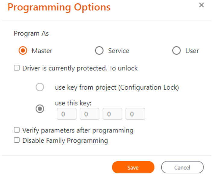
Programming options allow assigning programming roles:
-
Program As Master (default) allows programming all features and parameters by presenting a master password for unlocking.
-
Program As Service only allows programming features and parameters with permission set to service or everybody. Please make sure, that features that are not granted service permissions, have been excluded from programming by partial programming.
-
Program As User only allows programming features and parameters with permission set to everybody. Please make sure, that any features that need master or service permissions in the target driver have been disabled by partial programming - otherwise, programming will be rejected.
Programming options set in the production file will be used as default when programming drivers with Tuner4TRONIC Production. Programming options can be revised in Tuner4TRONIC Production at any time before programming.
When creating a production file, an unlock key (either master key, when programming as master or service key, when programming as service) can be set to unlock drivers and hence allow programming protected drivers. The unlock key can either be the same as the key used in the production file to protect the driver after programming (s. ConfigLock settings) or the user can select a different key for unlocking. The key for unlocking will be entered in the encrypted production file and will never be displayed by any T4T tools. If no unlock key has been set, unlock key can be entered manually in Tuner4TRONIC Production before programming protected drivers.
The programming option page also allows checking/unchecking the verify checkbox to force parameter verification after programming with T4T-Production via DALI to save programming time. When programming via NFC, parameter verification will be performed in any case - regardless of the setting in the checkbox).
T4T-Production allows programming drivers with production files created for drivers of the same family of previous driver generations (different basic code, i.e. first 7 digits of the driver IC) by calling a family conversion service. Family programming also allows programming drivers of same family but different power ranges if the data matches the parameter limits of the target driver. By checking the Disable Family Programming checkbox, T4T-Production will reject programming drivers with different basic codes.
3.6.2 Programming Drivers
Tuner4TRONIC Configurator allows creating production files. However, Tuner4TRONIC Configurator cannot be used to physically program drivers, since this is a browser-based application that cannot access the hardware interface on your local computer. For programming drivers, production files need to be imported in Tuner4TRONIC Production. To import production files, either open the production file in T4T-P or simply double-click on the production file downloaded by your browser (bottom left corner in Google Chrome).
See the T4T Production 4 user manual for driver programming and the Field App user manual for supported field adjustments.
Service contact
Inventronics GmbH
Parkring 31-33
85748 Garching, Germany
Phone: +49 89 6213-0
www.inventronicsglobal.com
Tuner4TRONIC support: T4Tsupport@inventronicsglobal.com